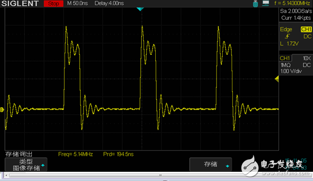
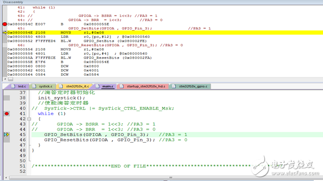
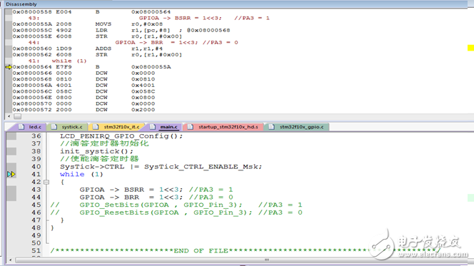
This article compares and tests the read and write IO time of STM32 by operating registers and calling library functions. Hardware environment Main control chip: STM32F103ZET6 External crystal oscillator: 8MHZ System frequency: 72MHZ 1. Read IO by operating the register Software online debugging interface Oscilloscope output waveform Analysis: Circulate the output level of PA3 in while (1). Through online debugging, one C statement can be seen: GPIOA -> BSRR = 1 Corresponding to 3 assembly instructions: MOVS r0, #0x08; transfer the immediate value 0x08 to the register r0 LDRr1,[PC,#8]; read a word from address (PC+8) to register r1 STRr0,[r1,#0x00]; Store the low byte in r0 to address (r1+0) Since most of the assembly instructions of Cortex-M3 are single-cycle instructions, in theory, the PA3 output high level is 3 clock cycles. That is, 3*(1/72)us = 42ns, the output high level time measured by the oscilloscope is about 42ns. Note: The measured output low level time of the oscilloscope is obviously longer than the output high level time. The reason is that each cycle ends, a new while loop judgment must be performed, that is, while (1) judgment also wastes time, almost 8 instruction cycles about. 2. Read IO by calling library functions Software online debugging interface Analysis: Circulate the output level of PA3 in while (1). Through online debugging, one C statement can be seen: GPIO_SetBits(GPIOA, GPIO_Pin_3);//PA3 = 1 The corresponding assembly instruction is: MOVSr1,#0x08 LDRr0,[pc,#12] BL.WGPIO_SetBits(0x080002FE) The third assembly instruction is a jump instruction, that is, jump to the address of the function GPIO_SetBits() to continue execution. The time taken to execute GPIO_SetBits(GPIOA, GPIO_Pin_3);//PA3 = 1 can be measured by an oscilloscope. From the output waveform of the oscilloscope, the waveform period is 708ns, minus the while(1) loop jump instruction 110ns, it takes about 300ns to output the high and low levels by calling the library function, which is 21 clock cycles, which is more than the direct operation of the register. About 260ns. 3.STM32 interrupt time test Enable the tick timer Systick, configure to generate an interrupt every 1us, the interrupt service function is empty, and test the time from generating an interrupt, protecting the scene, entering the interrupt service function, and restoring the scene. Software online debugging interface From the output waveform of the oscilloscope, it can be calculated that the time to save the scene, enter the interrupt service function, and restore the scene is (475-195) about 280ns, which is about 20 clock cycles. Configure the tick timer with different interrupt periods. When the measured minimum period is 1us, 72 is counted, the interrupt can be entered normally, and the program is normal. If the timing period is less than 1 us, the timing time is inaccurate, and the timing period is close to 1 us. The reason is that the timing time is too short and the kernel cannot respond to the interrupt. IEEE 1394/Firewire Connector Overview
Fire Wire (IEEE 1394) Connector Wire to Borad Connectors
IEEE 1394 Connector Application:
Cameras 1394 Connector,Ieee 1394 Connectors,1394 Usb Connector,1394 Pcb Connector,Firewire Connector,IEEE 1394 USB Connector,1394 Firewire Connector ShenZhen Antenk Electronics Co,Ltd , https://www.antenkconn.com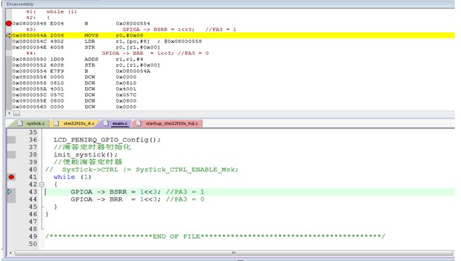
Oscilloscope output waveform 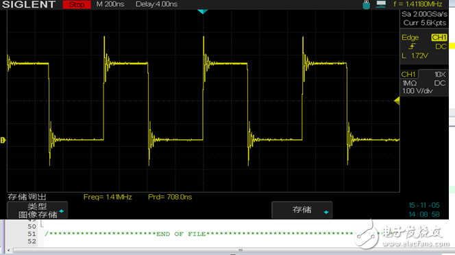
Oscilloscope output waveform 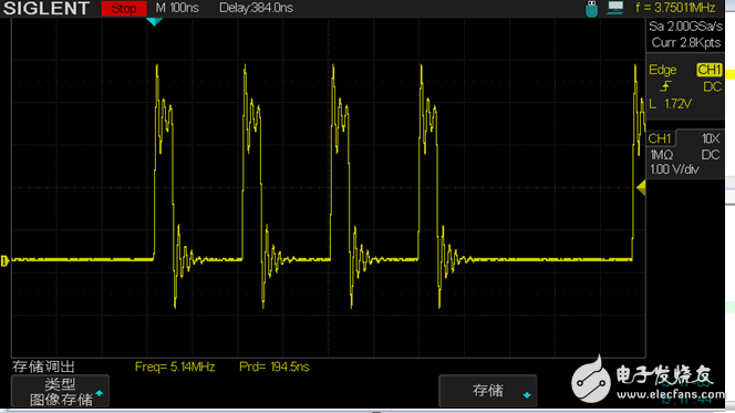
The IEEE 1394 connector series is capable of accommodating data rates up to 400 megabytes per second for serial transmission-consists of six-position connectors (for connections of computers to peripherals), and four-position connectors (for connections of digital AV equipment. We offer a screw thread size of M1.6 and two types of headers: dual inline package (DIP) and surface-mount technology (SMT). These four-position connectors help us manage a wide range of device designs and are suitable for DVD, set-top box, etc. The cable assemblies are also available with four-position to four-position type, for connection of AV equipment; four-positions to six-positions of transition type, for connections of PC and AV equipment; and six-position to six-position type for connections of PC and peripherals.
IEEE 1394 Connectors Product Features
Conforms to IEEE 1394 standard
Easy connections for plug and play devices
Available for wide range of connectors
DIP and SMT types available for PCB side
For 0.8mm and 1.6mm PC boards, M1.6 and M2.1 (4-position) panel mounting screw thread sizes
Use for automatic mounting machines with embossed tapes (4-position)
No of Contacts 4, 6, 9
Type
4pin IEEE 1394 Connector Female PCB Mounting Straight
4pin IEEE 1394 Connector Female PCB Mounting Right Angle
6pin IEEE 1394 Connector Female PCB Mounting Straight
6pin IEEE 1394 Connector Female PCB Mounting Right Angle
4pin IEEE 1394 Connector Male Wire Moulding type
6pin IEEE 1394 Connector Male Wire Moulding type
9pin IEEE 1394 Connector Male Wire Moulding type
9pin IEEE 1394 Connector Female PCB Mounting Right Angle
IEEE 1394 Connector With Female SMT 04P
IEEE 1394 Connector With Female SMT 09P
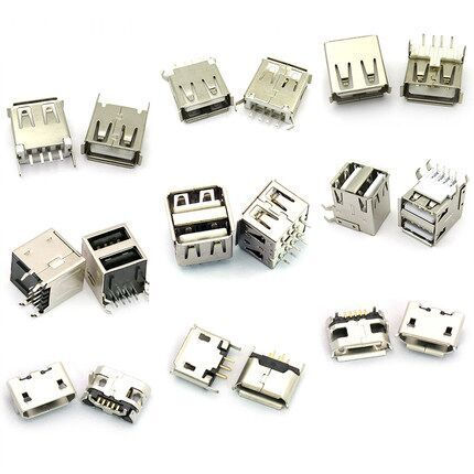
IEEE1394 (Firewire) interface, IEEE1394 is a serial standard. .Like USB, IEEE1394 also support hotplug peripherals and can provide power for peripherals,
eliminating the need for built-in power supply. IEEE1394 supports multiple devices as well as synchronous data transmission.
Camcorders
Scanners
Printers
DVD Players
Set-Top Boxes
Computer Monitors
Audio Video Receivers
Hard Drives
Audio Recording Devices