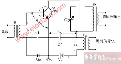
Collector AM circuit diagram In the figure, let the base excitation signal voltage (ie carrier voltage) be: υo = Vocosωot For more details, please check: Collector Amplitude Modulation and Large Signal Detection Experiment 3 Phase DIN Rail Energy Power Meter 3 Phase Din Rail Energy Power Meter,Din Rail Power Meter,Din Rail Electric Meter,Din Rail Mounted Electricity Meters TRANCHART Electrical and Machinery Co.,LTD , https://www.tranchart-electrical.com
Then the instantaneous voltage applied between the base emitter is υB = —VBB + Vocosωot
The modulation signal voltage υΩ is added to the collector circuit and connected in series with the collector DC voltage VCC. Therefore, the effective power supply voltage of the collector is VC = VCC + υΩ = VCC + VΩcosΩt = VCC (1 + macosΩt)
In the formula, VCC is the fixed power supply voltage of the collector; ma = VΩ / VCC is the amplitude modulation index