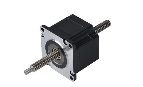
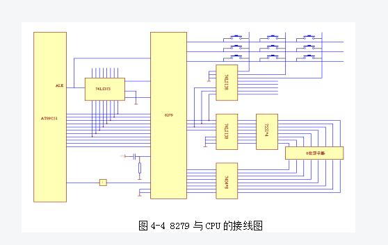
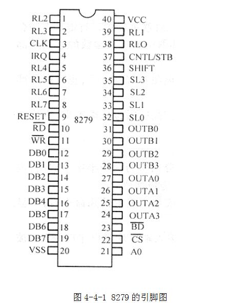
Stepper motors are open-loop control elements that convert electrical pulse signals to angular or linear displacements. In the case of non-overloading, the speed of the motor, the position of the stop depends only on the frequency and number of pulses of the pulse signal, and is not affected by the load change, ie a pulse signal is applied to the motor and the motor rotates through a step angle. The existence of this linear relationship, coupled with the fact that the stepper motor has only periodic errors and no cumulative errors, is a feature. It is very simple to use a stepper motor to control the speed and position. Stepper motor speed control is generally to change the frequency of the input stepper motor pulse to achieve stepper motor speed control, because the stepper motor for each pulse to rotate a fixed angle, so that you can control the stepper motor A pulse to the next pulse interval to change the pulse frequency, the length of the delay to specifically control the step angle to change the motor speed, in order to achieve stepper motor speed, this article mainly introduces the stepper motor based on the microcontroller speed Detailed control design, the article is attached to the program. In this design, the CPU used 89C5l as the control chip for the stepper motor. The 89C51 is simple in structure and can achieve flashing EEPROM on the programmer for tens of thousands of times. Convenient to use, etc., and is fully compatible with all functions of MCS5l series microcontrollers. The AT89C51 is a low voltage, high performance CMOS 8-bit microprocessor with a 4K byte Flash Programmable Erasable Read Only Memory (FPEROM-FAlsh ProgrAmmABle And ErAsABle ReAd Only Memory), commonly known as a microcontroller. The device is manufactured using ATMEL's high density non-volatile memory manufacturing technology and is compatible with the industry standard MCS-51 instruction set and output pins. With the combination of a multi-function 8-bit CPU and flash memory in a single chip, ATMEL's AT89C51 is an efficient microcontroller that provides a flexible and inexpensive solution for many embedded control systems. The display circuit is driven by an 8279 chip, and the 8279 chip is connected to two rows of displays, each row being a 4-bit display, which is used to display the actual rotation speed and the given rotation speed of the stepping motor. The connection between the 8279 and the CPU is shown in Figure 4-11. The specific introduction of the 8279 chip is as follows; 1) DB0~DB7: Bidirectional data bus. The CPU transmits data and commands at 827. 2) CLK: 8279 system clock, 100KHZ is the best choice. 3) RESET: Reset input line, active high. When the RESET input goes high, 8279 is initially reset. 4) /CS: chip select signal. Low level enable, write command to 8279 or read 8279 data when enabled. 5) A0: Used to distinguish the characteristics of information. When A0=1, the CPU writes a command to 8279 or reads the status of 8279; when A0 is 0, it reads and writes a data. 6) /RD: Read the control line. /RD=0,8279 will send data to the external bus. 7) /WR: Write the control line. /WR=0,8279 will capture data from the external bus. 8) IRQ: Interrupt request output line, active high. When the FIFO RAM buffer stores the key code of the closed key on the keyboard, the IRQ line rises and requests the CPU for the interrupt. When the CPU reads the data of the input key number in the buffer, the interrupt request line drops to low. Level. 9) L0 to SL3: Scan output lines for scanning the keyboard display. It can be a coding mode (16 to 1) or a coding mode (4 to 1). 10) RLRL7: Feedback input line pulled high by the internal pull-up resistor, or pulled low by the keys on the keyboard. 11) FT, CNTL/STB: The input line of the control key is pulled high by the internal pull-up resistor, and it can also be pulled low by the external control button. 12) TB0~3, OUTA0~3: Display segment data output lines, which can be output as two half-bytes, or as 8-bit segment data output ports. OUTB0 is the lowest bit and OUTA3 is the highest bit. 13) Blanking output line, active low. Blanking is displayed when the monitor switches or when blanking commands are used. The 8279 initialization procedure is as follows: INIT: MOV DPTR, #7FFFH; Set 8279 Command/Status Port Address MOV A, #0D1H ; Set clear display command word MOVX @DPTR,A ; Send display command WEIT: MOVX A, @DPTR; Read Status JB ACC.7, WEIT ; Wait for clear display RAM to end MOV A, #34H; Set the frequency division factor, crystal 12MHz MOVX @DPTR,A ;send frequency division coefficient MOV A, #00H ; Set keyboard/display commands MOVX @DPTR,A ; Send keyboard/display commands MOV IE, #84H ; Allow 8279 Interrupts RET The display subroutine is as follows: DIS: MOV DPTR, #7FFFH; Set 8279 Command/Status Port Address MOV R0, #30H; field code first address MOV R7, #08H ; 8-bit display MOV A, #90H ; Set Display Command Word MOVX @DPTR, A ; Send display command MOV DPTR, #7FFEH; Set the data port address LP: MOV A, @R0 ; Take display data ADD A,#6 ;Add offset MOVC A, @A+PC; lookup table to obtain the data segment code MOVX @DPTR,A ;Send segment code display INC R0 ;Adjust data pointer DJNZ R7, LP; RET SEG: DB 3FH, 06H, 5BH, 4FH, 66H, 6DH ; character 0, 1, 2, 3, 4, 5 segment code DB 7DH, 07H, 7EH, 6FH, 77H, 7CH ; character 6, 7, 8, 9, A, B section code DB 39H, 5EH, 79H, 71H, 73H, 3EH ; Characters C, d, E, F, P, U segment code DB 76H, 38H, 40H, 6EH, FFH, 00H ; characters H, L, -, Y, "empty" segment code The keyboard interrupt subroutine is as follows: KEY:PUSH PSW PUSH DPL PUSH DPH PUSH ACC PUSH B SETB PSW.3 MOV DPTR, #7FFFH; Set Status Port Address MOVX A, @DPTR ; Read FIFO status ANL A, #0FH; JZ PKYR ; MOV A, #40H ; Read FIFO Command MOVX @DPTR,A ; Send FIFO command MOV DPTR, #7FFEH; Set the data port address MOVX A, @DPTR ; Reading data LJMP KEY1 ; key value handler PKYR: POP B POP ACC POP DPH POP DPL POP PSW RETI; KEY1: ... ... key value handler List of keyboard programs: KEY1: ACALL KS1 ; There is no key to press the subroutine JNZ LK1; There is a key press, go to delay AJMP KEY1 ; No key pressed to continue scanning LK1: ACALL DELA12 ; 12ms delayed program call ACALL KS1 ; judge whether the key is really pressed JNZ LK2; with key press, go to column scan AJMP KEY1 ; No key pressed to continue scanning LK2: MOV R2, #0FEH ; Setting the First Column Scan Word MOV R4, #00H ; Save the first column number LK4: MOV DPTR, #7F01H; column scan words sent to the PA port MOV A, R2 MOVX @DPTR,A INC DPTR; point to the PC port INC DPTR MOVX A, @DPTR ; Read line status JB ACC.0, LONE; Line 0 No key press, turn LONE MOV A, #00H ; There is a key press, set the first key number AJMP LKP ; Transfer key number LONE: JB ACC.1,LTWO; 1st row without key press, turn LTWO MOV A, #08H ; There is a key press, set the first key number AJMP LKP ; Transfer key number LTWO: JB ACC.2, LTHR; line 2 without key press, turn LTHR MOV A, # 10H ; There is a key press, set the first row of keys? AJMP LKP ; Transfer key number LTHR: JB ACC.3, NEXT ; 3rd line without keys, check the next column MOV A, #18H; There is a key press, set the first row of keys LKP: ADD A, R4 ; find key number, key number = first row number + column number PUSH ACC ; protection key number LK3: ACALL KS1; waiting for key release JNZ LK3; key is not released, continue to wait POP ACC; key release, key number send A AJMP OVER; key scan ended NEXT: INC R4; column number plus 1, point to next column MOV A, R2 ; Judge whether 8 columns have been scanned JNB ACC.7, KND; 8 columns scanned, continue RL A ; scan word left shift one MOV R2,A ;Send scan word AJMP LK4 ; Scan the next column KND: AJMP KEY1 OVER: RET; key scan ended KS1: MOV DPTR, #7F01H ; Point to the PA port MOV A, #00H ;Set scan word MOVX @DPTR,A ; Scan words sent to the PA port INC DPTR; point to the PC port INC DPTR MOVX A, @DPTR ; Read the status of the PC port CPL; high level indicates that there is a key down ANL A, #0FH ; Shield high 4 digits RET The initialization procedure is as follows: INIT: MOV DPTR, #7FFFH; Set 8279 Command/Status Port Address MOV A, #0D1H ; Set clear display command word MOVX @DPTR,A ; Send display command WEIT: MOVX A, @DPTR; Read Status JB ACC.7, WEIT ; Wait for clear display RAM to end MOV A, #34H; Set the frequency division factor, crystal 12MHz MOVX @DPTR,A ;send frequency division coefficient MOV A, #00H ; Set keyboard/display commands MOVX @DPTR,A ; Send keyboard/display commands MOV IE, #84H ; Allow 8279 Interrupts RET The display subroutine is as follows: DIS: MOV DPTR, #7FFFH; Set 8279 Command/Status Port Address MOV R0, #30H; field code first address MOV R7, #08H ; 8-bit display MOV A, #90H ; Set Display Command Word MOVX @DPTR,A ; Send display command MOV DPTR, #7FFEH; Set the data port address LP: MOV A, @R0 ; Take display data ADD A,#6 ;Add offset MOVC A, @A+PC; lookup table to obtain the data segment code MOVX @DPTR,A ;Send segment code display INC R0 ;Adjust data pointer DJNZ R7, LP; RET The keyboard interrupt subroutine is as follows: KEY:PUSH PSW PUSH DPL PUSH DPH PUSH ACC PUSH B SETB PSW.3 MOV DPTR, #7FFFH; Set Status Port Address MOVX A, @DPTR ; Read FIFO status ANL A, #0FH; JZ PKYR ; MOV A, #40H ; Read FIFO Command MOVX @DPTR,A ; Send FIFO command MOV DPTR, #7FFEH; Set the data port address MOVX A, @DPTR ; Reading data LJMP KEY1 ; key value handler PKYR: POP B POP ACC POP DPH POP DPL POP PSW RETI; Design of drive circuit subroutines PUSH:MOV R3 , # NUM PUSH A PUSH PSW LOOP: SETB P1.0 ACALL DELAY1 CLR P1.0 ACALL DELAY2 DJNZ R3, LOOP POP PSW POP A RET Delay subroutine design MOV R2, #18H LCALL 7FEBH RET ORG 7FEBH ; Universal Delay Subroutine (07EBH & 0FEBH &...) L7FEB: PUSH 02H; R2 (R2 is 02H after reset) Stored time constant, stack protection L7FED: PUSH 02H ; R2 push protection L7FEF: PUSH 02H ; Pushing L7FF1: DJNZ R2,$; R2 is not zero waiting POP 02H ; DJNZ R2,L7FEF ; R2 is not zero transfer POP 02H ; Out DJNZ R2,L7FED ; R2 is not zero transfer POP 02H ; Out DJNZ R2,L7FEB ; R2 is not zero transfer RET; Subroutine return END Figure 6-4-1 Main program flow chart The main program is as follows: CON: MOV R3, # N MOV TMOD, # 10H MOV TL1 , # LOW MOV TH1 , # H IGH JNB FLAG ,LEFT MOV R0 , RM AJMP TIME - S LEFT: MOV R0, LM TIME: SETB EA SETB ET1 SETB TR1 Stepping motor control program p3.2 forward rotation, p3.3 reverse, p3.4 stop stepping motor connection p1.0p1.1p1.2p1.3 Org 00h Stop: orl p1,#0ffh ; Stepper motor stop Loop:jnB p3.2,for2 ; if p3.2 press forward jnB p3.3, rev2 ; if p3.3 presses reverse jnB p3.4, stop1 ; if p3.4 is pressed to stop Jmp loop ; repeatedly monitor the keyboard For: mov r0, #00h ; is turning to the initial value of the tAB code grab pointer For1:mov A,r0; Mov dptr, #tABle ; movC A, @A+dptr Jz for ; whether the end code 00h Cpl A ; Reverse ACC Mov p1,A ; output to p1 starts forward jnB p3.4, stop1 ; if p3.4 is pressed to stop jnB p3.3, rev2 ; if p3.3 presses reverse CAll delAy ; speed of rotation inC r0 ; Take a code Jmp for1 ; continue to forward Rev:mov r0,#05h ;Reverse to the initial value of the tAB code grab pointer Rev1:mov A,r0 Mov dptr,#tABle ;Fetch code movC A, @A+tABle Jz rev ; whether the end code 00h Cpl A ; Reverse ACC Mov p1,A ; output to p1 starts to reverse jnB p3.4, stop1 ; if p3.4 is pressed to stop jnB p3.3, rev2 ; if p3.3 presses reverse CAll delAy ; speed of rotation inC r0 ; Take a code Jmp rev1 ; continue to reverse Stop1:CAll delAy ; Debounce by p3.4 jnB p3.4,$ ; p3.4 release? CAll delAy ; Release to eliminate jitter Jmp stop For2:CAll delAy ; Debounce by p3.2 jnB p3.2,$ ; P3.2 release? CAll delAy ; Release to eliminate jitter Jmp for Rev2:CAll delAy ; Debounce by p3.3 jnB p3.3,$; P3.3 release? CAll delAy ; Release to eliminate jitter Jmp rev delAy:mov r1,#40; stepper motor speed 20ms D1: mov r2, #248 Djnz r2,$ Djnz r1,d1 Ret tABle: dB 03h,09h,0Ch,06h ; Forward table dB 00 ; Forward end dB 03h,06h,0Ch,09h ; Reverse dB 00 ; End of reversal End Stepper motor positive and negative speed program Org 00h X1:mov r3,#48;48 steps stArt:mov r0,#00h ; Forward code initial value stArt1: Mov p1, #0ffh ; stop first Mov A,r0 Mov dptr,#tABle movC A, @A+dptr Jz stArt ; Is the end code 00? Cpl A Mov p1,A ; output operation CAll delAy ; Invoke slow delay rotation inC r0 ; code acquisition pointer plus 1 to remove the next code Djnz r3,stArt1 ;Whether it took 48 steps? Mov r3,#48; yes reset 48 steps stArt2: Mov p1,#0ffh Mov r0, #05 ; Reversed initial code fetch stArt3:mov A,r0 Mov dptr,#tABle movC A, @A+dptr Jz stArt2 Cpl A Mov p1,A CAll delAy2 inC r0 Djnz r3,stArt3 Jmp x1 ; Repeat start DELAY: ; Delay procedure (slow) MOV R7, #255 D1: MOV R6, #50 D2: DJNZ R6, D2 DJNZ R7, D1 RET DELAY2: ; Delay program (fast) MOV R5, #255 D3: MOV R2, #25 D4: DJNZ R2, D4 DJNZ R5, D3 RET tABle: dB 03h,09h,0Ch,06h ; Forward table dB 00 dB 06h,0Ch,09h,03h ; Reverse Table dB 00 End The interrupt service routine is as follows: INTTO: PUSH A PUSH PSW MOV A , @R0 MOV P1 ,A INC R0 MOV A , # 00H XRL A , @R0 JNZ NEXT MOV A , R0 CLR C SUBB A, # 03H MOV R0 , A NEXT: DJNZ R3 , RETU CLR ET1 CLR EA RETU: POP PSW POP A RETI List of programs that use software to form a pulse sequence: PULSE_S: MOV R7,#NUM ; set the number of pulses PUSH A; protect the scene PUSH PSW LOOP: SETB P1.0 ; output high ACALL DELAY1 ; Delay CLR P1.0 ; Output low level ACALL DELAY2 ; Delay DJNZ R7, LOOP ; R7 ≠0, continue to output pulse POP PSW;Restoration POP A RET Timed interruption subroutine TIME0: CLR EA ; Off Interrupt INC 30H MOV A, 30H XRL A,#50H ;Judge to 8 seconds JZ S_8; 8 seconds arrives, go to S_8 AJMP RECOUN; 8 seconds have not elapsed, continue timing S_8: SETB P3.2; trigger external interrupt 0 NOP CLR P3.2 NOP RECOUN: MOV TH0, #3CH MOV TL0,#0B0H ;Set initial value of timer SETB EA; On interrupt RETI; interrupt return Interrupt routine T_CON: PUSH A; protect the scene PUSH PSW MOV R7, #N ; Set the number of control steps JNB FLAG,LEFT ;Judge rotation direction RIGHT: MOV R0, RM ; forward start of model AJMP ROTATE LEFT: MOV R0,LM ROTATE: MOV A, @R0 ; Take the first shot control model MOV P1, A ; output first beat control model ACALL DELAY1 ; Delay INC R0 MOV A, @R0 ; Take second shot control model MOV P1, A ; output second shot control model ACALL DELAY1 ; Delay INC R0 MOV A, @R0 ; Take the third shot control model MOV P1, A ; output third shot control model ACALL DELAY1 ; Delay DJNZ R7, ROTATE ; Did not go through the required number of steps, continue POP PSW;Restoration POP A RET ; Return Reverse Conducting Thyristor(RCT)
Reverse Conducting Thyristor(RCT) is also called Reverse- appreciation Thyristor.The characteristic is that a diode is connected in reverse parallel between the anode and cathode of thyristor, so that the transmitting junction of anode and cathode is short-circuited.As a result of this special circuit structure, it has high voltage resistance, high temperature resistance, short turn-off time, low switching voltage and other good performance.For example, the turn-off time of the reverse thyristor is only a few microseconds, and the working frequency is dozens of KHZ, which is better than the fast thyristor (FSCR).This device is suitable for switching power supply and UPS uninterrupted power supply. One RCT can replace one thyristor and one continuous current diode respectively.
Reverse Conducting Thyristor,Original Reverse Conducting Thyristor,New Reverse Conducting Thyristor,Reverse-Conducting Thyristor 2200V YANGZHOU POSITIONING TECH CO., LTD. , https://www.cnfudatech.com

