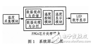
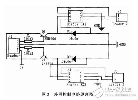
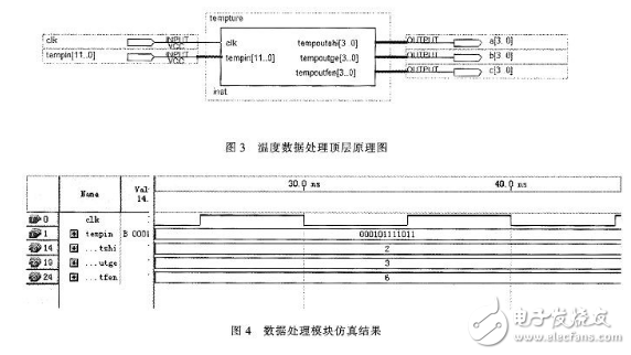
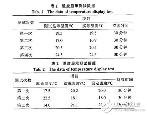
With the increasing popularity of industrial control automation, temperature control in the working environment is becoming more and more important. This design is an automatic temperature acquisition and control system designed for some special environments that require continuous constant temperature. The system uses FPGA as the core part of the hardware, effectively utilizes the advantages of FPGA in programmable gate arrays, makes the hardware circuit software to the greatest extent, reduces the scale of visual hardware, and reduces hardware processing, wiring and component procurement. The cost and complexity of the system reduces the complexity of troubleshooting. Make the hardware circuit concise and reduce the overall space occupied. Compared with other temperature control systems, it has the advantages of compactness and convenient maintenance and repair, which greatly improves maintainability. At the same time, because the components used are more common, the overall cost is lower. Therefore, it is very suitable for some small-scale occasions that do not require high temperature accuracy. The sensor realizes the collection of the external environment temperature, and transmits the collected temperature signal to the FPGA chip. The FPGA chip can independently process the collected temperature signal, and can display the current temperature through the LED, and at the same time automatically the collected temperature The signal is compared with the preset temperature to get the correct comparison result, and the peripheral temperature is controlled by the I/O port output control peripheral device, so as to achieve the purpose of real-time temperature control. In this design, there are mainly three parts: temperature acquisition module, FPGA chip module, and LED digital display module. The system principle block diagram is shown in Figure 1. Realize the real-time temperature data collection of the temperature sensor through FPGA programming, and process the collected data in real time, convert the collected data into BCD code, and display the previous temperature through an 8-segment LED digital tube. At the same time, the collected data will be compared with the temperature preset value stored in the chip, and the comparison result will be automatically generated, and the peripheral equipment will be controlled to adjust and control the temperature of the measured space, so as to achieve the purpose of constant temperature. The temperature sensor collects The output temperature data is displayed by LED through the binary array chip selection selection data, and the selected data is compared with the standard temperature. If the temperature is too high, the temperature will be reduced, and if the temperature is too low, the temperature will be increased. The control module is shown in Figure 2. The function of the two PNP transistors is to switch when P1 outputs the control signal. According to the transistor connection in the figure, when the output control signal is low, the transistor is turned on. There is current through the P2 relay, making its 3 and 6 pins connected. In the design, the transistor used in the design has high requirements for current, and because the inside of the relay can be considered as an inductance, when the relay is just powered on, the current of the emitter and collector of the transistor will be very large, and it is easy to change the transistor. Burn out, so install the voltage stabilizer diode D2 to make the relay work, the instantaneous current flows through the diode loop instead of through the transistor, which can effectively protect the transistor from being burned. When the external output signal is low, the p2 loop is turned on, pin 6 and pin 3 have current, and p3 is turned on and starts to work. When the temperature is too low, the bulb lights up; when the temperature is too high, the fan works. So as to realize the real-time control of temperature. In this design, FPGA chip is used as the core control part. In this design, the software modules mainly include temperature sensor control and data receiving modules, temperature data processing modules, and temperature display modules. 3.1 Temperature data processing module The top level circuit diagram of the sensor data processing module tempture is shown in Figure 3. Its main function is to convert the 12-bit binary temperature signal into a 3-digit decimal number represented by the BCD code, and the upper 8 bits of the input 12-bit temperature signal The binary code is converted into two groups of 4-digit BCD codes. For example, the input binary code is "00010110", which means the decimal number is "22", and the output BCD code is "00100010". And "2"; then convert the remaining low 4-bit binary code to 4-bit BCD code. If the input binary code is "1110", it means that the decimal number is "0.875". If only one decimal place is taken, then Take "8" and its BCD code can be expressed as "1000". The tens digit, the ones digit and the decimal place are respectively output through the three output ports. Perform simulation test on temperature data processing module tempture-. Assuming that the preset input temperature binary code is "000101111011", the corresponding decimal number should be: "23.6". The simulation result is shown in Figure 4. According to the top-level schematic diagram, a [3. 0] is the tens digit of the temperature value, b[3..0] is the one digit of the temperature value, and c[3..0] is the decimal place of the temperature value. In the simulation diagram, the three output numbers of shi, fen, and ge are "2", "3", and "6" respectively, and the simulation results are consistent with the predicted conversion results. 3.2 Temperature display module The design uses 4 8-segment LED digital tubes that can dynamically display the hundreds, tens, ones, and minutes of the temperature. The figure below shows the top-level circuit of the temperature display module. It can be seen from the figure that the module is composed of a chip selection module, a decoding conversion module and a counter. The chip selection module is mainly composed of a binary counter and a four-to-one circuit. When the system is working, first, the binary counter is controlled by clk to generate 4 two-bit binary arrays successively to control the selective output of the chip select module shi[3..0], ge[3..0], fen[ 3.. 0], bai [3.. 0] Any one of the four input signals. The selected input signal is delivered to the decoding conversion module, and the continuous binary array generated by the binary counter can be used to control the decoder to output the corresponding 4-bit binary array in turn to light up each LED nixie tube in turn. Finally, the number can be displayed on the LED and the result can be read. Perform software simulation test on the temperature display module display, set the input shi[3..0], fen[3..0], and ge[3..0] to be "0100", "0011", and "0010" respectively, then The corresponding decimal number should be "43.2". The simulation result is shown in Figure 6. It can be seen from the simulation diagram that the chip select signal is cyclically controlled by the clock signal, and the corresponding output ledout terminal also outputs the input data of the four ports shi, fen, ge, and bai in turn, and the output is an 8-bit LED digital tube display The code can be read from the figure. When the chip select signal is "0111", the corresponding output signal ledout is "11000000", which means that the display on the digital tube is 0, and the decimal point is not bright, indicating that the hundreds place is 0; When the chip select signal is "1011", the corresponding output signal ledout is "10011001", the display on the digital tube is 4, and the decimal point is not bright, indicating that the tens place is 4; when the chip select signal is "1101", the corresponding The output ledout is "10110000", the display on the digital tube is 3, which means the ones place is 3; when the chip select signal is "1110", the corresponding output ledout is "00100100", and the display on the digital tube is 2 , The decimal point lights up, indicating that the decimal place is 2. After dynamic scanning, it can be known that the content displayed on the digital tube is "043.2". It is the same as the input data, indicating that the program is written correctly and the system is operating well. According to the data in Table 1, the temperature displayed on the LED digital tube and the actual measured temperature can be drawn from the table, the two are approximately equal, and the error is between 0% and 0.58%, which is an acceptable error range. Table 2 refers to setting the required temperature, recording the process of temperature changes and the time required to achieve this goal. For example, in the first time, we set the temperature to 20°C, and the temperature value displayed on the LED was 17.5°C. Finally, the temperature was raised to 20.2°C through the automatic control system. This process takes 30 minutes. The error also exists, the error is about 1%, which is also an acceptable range. From the test results, the main purpose of the design has been achieved, the system runs reliably, and the accuracy has also reached the design requirements. However, there are still some defects in the design. The main defect is that the preset temperature used in this design is solidified in the program. Once the system starts to work, the preset temperature cannot be changed. Therefore, this system is more suitable for frequent changes. When setting the temperature. When changing the set temperature.
Features
A push button switch is a switch that has a knob that you push to open or close the contacts. In some pushbutton switches, you push the switch once to open the contacts and then push again to close the contacts. In other words, each time you push the switch, the contacts alternate between opened and closed. These types are commonly called latching switches. There are also Non latching push button switches that only maintain the switch contacts when the switch is help in position. Once the switch is let go, the current is broken and the switch turns off. Push switches are usually a simple on-off switch.
Push Switch,Push Button Switch,Micro Push Button Switch,Waterproof Push Button Switch Ningbo Jialin Electronics Co.,Ltd , https://www.donghai-switch.com


