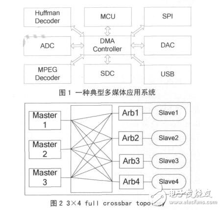
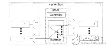
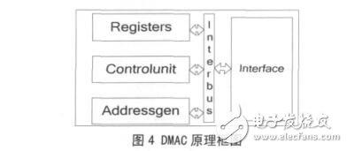
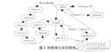
The DMA controller is added to the arbitration module to sort multiple transmission requests, and the configuration time and number of interruptions of the CPU are reduced by the memory configuration mode, but the bandwidth requirement for multi-tasking transmission is not guaranteed; the transmission task is also divided into real-time tasks and For non-real-time tasks, real-time transmission of the system is implemented according to real-time priority, but the system still needs to prioritize tasks and occupy system processing time; through pre-access and write loops, adding re-arrangement unit, chain mode and double buffering respectively And the use of different sizes of cache and other methods to improve the transmission efficiency of the DMA controller. However, these improved methods can only guarantee that the DMA controller transmits a single task at the same time. In order to realize the multi-task real-time transmission of the system, this paper proposes to introduce the Crossbar switching structure and design the corresponding multi-channel transmission DMA controller to ensure the multi-task transmission of the system. At the same time improve the real-time response of the system In order to introduce the design scheme of the multi-channel DMA controller in detail, the following is a detailed analysis of the working principle of the Crossbar-based multi-channel DMA controller. Then, the design and implementation of each module are specified, and then the design is verified and analyzed. And summarize. The traditional DMA controller adopts the shared bus mode to realize data transmission. The process of data transmission by the system is as follows: (1) First, the device issues a DMA request to the DMAC. (2) After receiving the device request, the DMAC issues a bus request to the CPU to request to take over the system bus. (3) The CPU sends a bus response signal to the DMAC after executing the current instruction cycle. (4) The CPU is out of control of the system bus, and the DMAC takes over the control system bus. (5) The DMAC sends an acknowledgement signal to the device. (6) The DMAC performs data transfer between the memory and the device. (7) When the set data is transferred, the DMAC cancels the bus request signal and leaves the control of the bus. After the CPU detects that the bus request signal becomes invalid, the CPU cancels the bus response signal, restores the control of the system bus, and simultaneously jumps. Go back to the state before the interruption. However, for a typical multimedia application system as shown in FIG. 1, there are a Huffman Decoder, an MPEG Decoder, a USB module, an SPI module, an SD card control mode (SDC), and a digital-to-analog conversion. Module (DAC), etc., Huffman decoding module and image decoding module need to communicate with USB module, SD card control module or SPI module, that is, there are several data transmissions at the same time and the module for transmitting data is changed, DMA using shared bus The controller cannot handle multiple channel tasks at the same time. The existing multi-channel DMA controller can only exchange data for fixed devices, so it is not suitable for such system requirements. For this type of application, this article introduces the Crossbar interconnect structure, replacing the shared bus with the Crossbar bus. Crossbars are called crossbar matrixes or crossbar switching matrices and do not block due to insufficient bandwidth resources [8]. Figure 2 shows the schematic of the full Crossbar bus topology. Due to the large number of connecting lines required for the full Crossbar bus, it is often simplified in practice to a part of the Crossbar bus topology, which removes the connection between modules that do not require communication to save space. Crossbar's interconnect structure is implemented in the interface module of MDMAC. As a local bus for DMA transfer, DMA transfer no longer occupies the system bus, so it can work in parallel with the CPU. All devices that need to transfer data in DMA mode are directly attached to the interface module. Since these devices also need to communicate with the system bus, each device needs to add a multi-channel selection unit to select signals from the system bus or Is the signal from MDMAC. The interface module of MDMAC implements the interconnection structure of the full Crossbar, and its connection with the device and the connection mode of the system bus are shown in Figure 3. Any device on the left side of the figure can perform DMA mode data transmission with any device on the right side of the figure. . Since the number of device ports in the interface module can be designed according to the specific application, it can be ensured that all DMA transmissions in the system can be performed in parallel without requiring a certain arbitration algorithm to be used for multiple SAR controllers. The transmission request is sorted so that the transmission time cannot be guaranteed, and the arbitration module introduces a large delay, making the transmission response slow. According to the basic principle of the above multi-channel DMA controller, the multi-channel DMA controller can be designed and implemented according to the structure of FIG. 4, and its constituent modules can be divided into four parts: register module Registers, control module Controlunit, address generation module Addressgen and interface. Module Interface. The specific design and implementation scheme of each module is described in detail below. The Registers register module aggregates various registers of the controller, including global registers and special registers for each channel. The interaction between the controller and the system microprocessor is mainly done by these registers. The global registers are valid for all channels, including configuration fetching, without the need for CPU involvement, until the entire descriptor list is executed and then an interrupt is generated to notify the CPU, whereas the traditional CPU configuration mode generates an interrupt every time a task is executed. The CPU configures the next task. There are two modes for each transmission. One is the software enable mode, that is, as long as the start bit of the register is set to 1 and the Idle state is started; the other is the hardware handshake mode. After the start position of the register is 1, it is required. A module with a transfer request sends a request and waits for MDMAC to confirm before the transfer begins. The software enable mode is suitable for data copy operations, and the CPU transfers data from one address range to another. The hardware handshake method is the traditional DMA working mode. Water-cooled capacitor is supercapacitor is a capacitor with a capacity of thousands of farads.According to the principle of capacitor, capacitance depends on the distance between the electrode and electrode surface area, in order to get such a large capacitance, as far as possible to narrow the distance between the super capacitor electrode, electrode surface area increased, therefore, through the theory of electric double layer and porous activated carbon electrode. Water-Cooled Capacitor,Water-Cooled Power Capacitor,Water-Cooled Electric Heat Capacitor,Water-Cooled Electric Heating Capacitor YANGZHOU POSITIONING TECH CO., LTD. , https://www.cndingweitech.com


Crossbar's multi-channel DMA controller design
1 Introduction