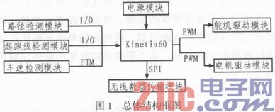
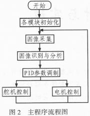
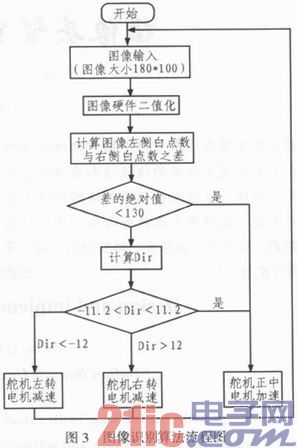
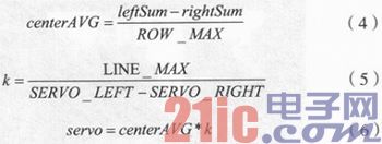
Abstract: The intelligent tracking car can identify the road condition based on the input image of the front camera. By optimizing the hardware and software design of the smart car, it can ensure the speed and accuracy of driving in different environments. This article uses Kinetis60 as the core processor. The design and implementation of the smart car path detection, speed detection, data transmission module and motor steering gear drive module are completed. Based on this, a method for judging the smart car tracking using the real-time image of the camera is proposed, which can extract accurate The path characteristic information proves that the method is feasible. This article refers to the address: http:// With the wide application of intelligent transportation systems, the system control of smart cars has gradually become an emerging technology, which covers control, pattern recognition, sensing technology, electronics, electrical, computer, mechanical and many other disciplines. The program uses the camera as a sensor for signal acquisition, and performs precise calculation based on the image acquired by the camera to determine the speed reference and steering steering reference. The smart car of the camera group has strong predictive ability for road information, and the camera has a fine detection of the road and a wide range of viewing angles, so it is welcomed by many smart car designers. However, the image of the camera is greatly affected by the surrounding light; the algorithm has a large amount of computation and the algorithm is complex, which requires more NCU resources. Therefore, the design of the image recognition algorithm becomes a key step in the system design. 1 system design The smart car system consists of core processor KINETIS60, path detection module, starting line detection module, vehicle speed detection module, power module, wireless data transmission module, motor drive module and servo drive module. The path detection module of the camera group is implemented by the OV7620 camera. The vehicle speed detection module is composed of an encoder to realize real-time speed acquisition. The motor drive module is realized by eight HRF3205s forming an H-bridge. The power module consists of three LM2940s. The servo is connected to the PWM pin using S-D5. The starting line detection module consists of two TCRT5000s and one LM339. Wireless data transmission is carried out by NRF24L01. The smart car collects the image of the road ahead by the path sensor, extracts useful information from it, determines the type of runway (straight road, big curve, S curve), and determines the steering and speed of the steering gear of the trolley. Thus, the motor and the steering gear drive the trolley to smoothly travel on the runway. The system block diagram is shown in Figure 1. 2 software algorithm overall design In this scheme, IAR is used as a development tool. The system software design includes the following aspects: system initialization, video image signal acquisition, trolley direction (steering gear) control and speed (motor) control. The system software flow is shown in Figure 2. 3 image acquisition The OV7620 is a CMOS color/black and white image sensor. It supports two scanning modes, continuous and interlaced, VGA and QVGA image formats; the highest pixel is 664×492; the data format includes YUV, YCrCb, and RGB, which can meet the requirements of general image acquisition systems. Since the chip processing capability is not enough to achieve the computing power of the PC, this scheme adopts a black-and-white camera. Due to the limitation of the on-chip bus frequency, the number of points that can be acquired per line is limited and the image quality is poor, and it takes up most of the CPU. Time, so we used the K60's own DMA for data acquisition. It has been proved that DMA can collect most points and the image quality is very good. In order to better detect the position of the black line center, it is necessary to ensure that there are enough points on a single line. In order to improve the processing speed, the number of sampling lines can be appropriately reduced, and the above conditions are comprehensively determined. Finally, it is decided to use 100 lines of information for direction judgment, and each image size Limited to 180 × 100. 4 image recognition The key to whether the camera smart car system can recognize the correct direction is the design of the image recognition algorithm. In this algorithm, according to the acquired image, the image is binarized first, and then the binarized image is denoised. Processing, obtaining an image containing only the black line of the track, and then performing image recognition on the image, and performing direction recognition according to the set threshold value, and the obtained result is sent to the steering control module to perform steering direction control. A path recognition flowchart based on an image recognition algorithm is shown in FIG. 4.1 Black line extraction Binarization is a widely used image segmentation technique that takes advantage of the difference in grayscale characteristics between the object to be extracted and the background of the image, and turns the original image into an image object represented by only two gray values. And the binary image of the background, considering the difference between the gray value of the acquired image object (black center line) and the background (white runway), the image is binarized by the fixed threshold method. The implementation of binarization is implemented by the following formula: Where g(x, y) is the binarization result; T is the threshold, and f(x, y) is the gray value of the original image. This scheme uses a fixed threshold for image binarization because the microcontroller does not have enough time for dynamic threshold calculation. Therefore, to determine a reasonable algorithm to determine a fixed threshold, the image threshold of the car under different lighting conditions is different, so the car calculates a fixed threshold every time it starts, as shown in Figure 4. 4.2 Steering gear and motor control algorithm After extracting the center line of the image, it is necessary to judge the type of the track according to the position of the center line, and distinguish the straight track, the S-shaped curve, and the left turn and the right turn. The use of cameras to identify roads has advantages in recognition performance. Relative to optoelectronic and electromagnetic sensors, there can be far-reaching distances. Track information is not judged based on single-line data, but is determined based on multiple lines of information for each image. According to the foregoing, each image is judged using 80 lines of information. According to the result of the binarized image, the number of white points on the left and right sides of the boundary is calculated by using the center of gravity of the image as the boundary (2, Equation 31, and then the left and right white points and leftSum, rightSum are compared, and then the difference is divided by the line. Number, get the track offset (Equation 4), according to the offset centerAVG size, the size of centerAVG can basically judge the current track situation, according to the track situation, multiply centerAVG by different coefficient k (Expression 5), The steering value (Equation 6) is obtained and then the direction control is performed. 5 Conclusion This paper proposes a camera-based intelligent tracking vehicle design and implementation method, which is simple in processing, takes up less MCU resources, and has high execution efficiency. The algorithms mentioned in this paper can also be used on other tracks with the features of this document. Through many practices, the correct recognition rate of the algorithm is over 93%, which has been adopted many times in the actual university smart car competition and achieved excellent results. However, the height and angle of the camera need further testing and adjustment to get better image acquisition. The algorithm still needs further optimization to improve the stability of the system. ALIBARBAR INGOT 9000 Dispsoable Vape
The Alibarbar Ingot series has launched 13 flavors, with mysterious blind box flavors waiting to be unveiled.
Eliquid capacity:22ml Ecig oil vape, disposable vape, Vaporizer Shenzhen Yingyuan Technology Co.,ltd , https://www.smartpuffvape.com


![]()


BANANA BUZZ – ALIBARBAR INGOT – 9000 PUFFS
Battery capacity:2350mah
Battery type:TESLA 18650
Puffs:up to 9000
Size:103x40x26mm
Net weight:90g
Coil resistance:1.3Ohm
Non rechargeable
LED display