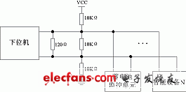
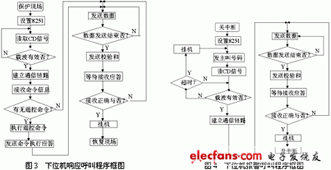
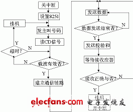
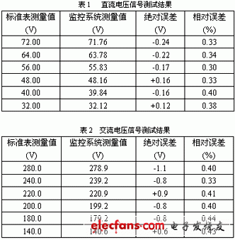
1 Introduction The "Technical Requirements for the Centralized Monitoring System of Communication Power Supply and Air Conditioning" stipulates that the monitoring system is a multi-level distributed computer monitoring network in structure [2], which can be generally divided into three levels, namely the monitoring center (SC-Supervision Center), monitoring Station (SS—Supervision StaTIon) and monitoring unit (SU—Supervision Unit). For the communication power supply monitoring system, there is no need to set up a monitoring center, so it can be simplified to a two-level distributed structure, consisting of the upper computer and the lower computer [1-2]. 2 Discussion on networking scheme of communication power monitoring system At present, the networking of the communication power monitoring system can mainly consider the following solutions: The first is the master-slave bus network that is still widely used. This network structure is centered on the upper computer, and various lower computers with communication functions are connected through the RS485 or RS422 interface. With the remote control function, the point-to-point serial communication (RS232) can be used between the lower computer and the smart device. The advantage of this structure is that it is very convenient to implement a small-scale monitoring system. The disadvantage is that the networking is limited by the communication distance. The second is the fieldbus network, which abandons the traditional master-slave network structure and realizes a truly fully distributed structure, so that each lower computer can be used as a peer node in the network. Meanwhile it It also provides an interface to the upper layer of the network, which can be easily connected to the SCADA system to achieve remote communication and remote download functions. The disadvantage is that when interconnecting with a computer, a special gateway is also required, and there are many standards that are difficult to popularize. The third is the Ethernet network. With the development of computer technology, Ethernet technology is currently used in some communication power supply monitoring systems. The Ethernet here refers to the peer-to-peer network generated by the interconnection of the lower computer and the upper computer directly through Ethernet. In this structure, not only are the lower computers equivalent, but the concept of the computer as the "upper computer" It also became very blurred. Compared with the previous two schemes, it has a higher speed, but its disadvantage is that it is expensive and difficult to apply to the communication power supply monitoring system. It can be seen from the above analysis that the traditional master-slave network is the most suitable for the networking of the communication power supply monitoring system, but due to the distance limitation, it must be improved. This system uses the existing PSTN network to solve this problem, that is, the communication between the lower computer and the upper computer is realized through the PSTN network, and the communication between the lower computer and the intelligent device is realized by RS485 to form a master-slave network. 3 Communication module hardware circuit design As the slave device directly facing the device, the lower computer needs to communicate with the upper computer remotely, and at the same time, the lower computer also needs to communicate with various intelligent devices as the master. Therefore, two communication methods, RS232 and RS485, are used in this system. The communication between the lower computer and the upper computer is realized by accessing the PSTN network through RS232, and the functions of obtaining parameters, transmitting data, and remote alarming are completed; the lower computer and each The communication between this kind of intelligent equipment is realized through RS485 networking to obtain data and its working status [4]. In this system, the communication module uses a separate microprocessor DS80C320, which also defines the second function for the P1 port on the basis of the ordinary single-chip, so as to have four full-duplex serial communication ports, six external interrupts, three A timer / counter, and it is fully compatible with 8051 in instructions, which is very suitable for the communication unit of the monitoring system. 3.1 Communication between lower computer and upper computer The communication between the lower computer and the upper computer uses the PSTN network as a medium, which can be achieved through the following three schemes: the first scheme is to use a dedicated Modem chip, and the Modem function is directly implemented in the lower machine; the second scheme is Extend a slot similar to PCI or ISA, connect to the PSTN network through the built-in Modem; the third is to expand a standard full-duplex RS232 communication interface, and connect to the PSTN network through the external Modem. Among the above three schemes, the first scheme has the advantages of low cost and easy integration design, but the disadvantage is that the design of software and hardware is more complicated and the system reliability is not high; the second scheme and the hardware design of the built-in Modem and expansion slot Closely related, not conducive to maintenance and upgrades; the third scheme has the advantages of good versatility, high reliability and easy maintenance, so the third scheme is adopted in this system to achieve communication between the lower computer and the upper computer. The specific implementation circuit is shown in Figure 1: Figure 1 DS80C320 and Modem hardware interface diagram In Figure 1, 8251 is a universal synchronous / asynchronous transceiver, which has independent receivers and transmitters, and can be programmed to communicate in simplex, half duplex, or full duplex. At the same time, it also provides multiple control signals, which can easily realize the interconnection with Modem. The 2MHz pulse is generated by the combination of DS80C320's ALE, and used as the clock signal of 8251. At the same time, this pulse is divided into 64 by the frequency divider composed of CD4024 and used as the receive and transmit clock of 8251. The chip selection signal of 8251 is connected to the address decoder 74LS138, and the control / data terminal is connected to the address line A0. Therefore, the addresses of the control word register and status word register of 8251 are BFFFH, and the data buffer address is BFFEH. RXD and TXD complete the data reception and transmission, and other control signals complete the state control and detection between the microcontroller and the Modem: the ringing indication signal RI is connected to the external interrupt of the DS80C320 after level conversion; the carrier detection signal CD is level converted Later connected to P1.1 of DS80C320. When the upper computer dials and calls the lower computer, the ringing instruction signal RI generates a ringing, which is an external interrupt source to generate an interrupt, the communication processor resets P1.1 to output a valid DTR signal, and goes off-hook to enter the state of answering communication. 3.2 Communication between lower computer and smart device RS485 master-slave communication is adopted between the lower computer and the intelligent equipment. RS485 uses balanced transmission and differential reception to achieve communication, and has strong anti-common mode interference capability. The transmission distance can reach 1.2 kilometers at a transmission rate of 10Kbps. The specific implementation plan is shown in Figure 2. Figure 2 The overall implementation of RS485 communication Pay attention to the following points when using this communication scheme: (1) A matching resistor should be connected at the end of the bus to absorb the reflected signal on the bus to eliminate glitches in signal transmission and ensure signal purity; (2) When there is no signal transmission on the bus, it is in a suspended state and is susceptible to interference. Therefore, a 10K resistor should be connected between the positive and negative terminals of the differential signal, between the positive terminal and the power supply, and between the negative terminal and ground. In this way, when there is no signal transmission on the bus, the positive terminal level is about It is 3.3V, and the negative terminal level is about 1.7V. At this time, even if there is an interference signal, it is difficult to generate the serial communication start signal "0"; (3) Because RS485 is a half-duplex communication method, sending and receiving share a channel, the system uses MAX485 to expand it, and the receiving and conversion functions are controlled by and DE, so a port line of the processor must be used Control how it works. As the MCU resets, each end The ports are all high-level, so you must pay attention to connect the port line to DE, and the reverse signal is connected to ensure that the master and slave are in the receiving state when the system is reset. 4 Communication module software design 4.1 Communication process between upper computer and lower computer The communication between the upper computer and the lower computer includes the active call of the upper computer, the response of the lower computer and the alarm call of the lower computer, and the response of the upper computer. The software flow is shown in Figure 3 and Figure 4 (only given The program flow of the lower computer part). 4.2 Communication process between lower computer and smart device Because RS485 is a half-duplex communication method, sending and receiving are done by the same device and the same channel, so the conversion of high and low levels of control signals is critical. This system uses the sending interrupt flag TI and the receiving interrupt flag RI of the single chip microcomputer as the reference for switching, but it must be ensured that the effective pulse width of the signal at the control terminal and DE is greater than the length of the signal sent or received in one frame. The specific software flow is shown in Figure 5. Figure 5 Local communication program block diagram 5 Experimental results The test results of the monitoring system are given by taking AC and DC voltages as an example (the standard table for testing is ESCORT3155A; the test ambient temperature is 180C). The test result of the DC voltage signal is shown in Table 1; the test result of the AC voltage (taking the A-phase AC input as an example) is shown in Table 2. From the above experimental results, it can be seen that the system has high measurement accuracy, and can fully meet the requirements in "Technical Requirements for Centralized Monitoring System of Communication Power Supply and Air Conditioning". 6 Conclusion The article first analyzes several main networking schemes currently in existence in the communication power supply monitoring system, and draws the conclusion that the traditional master-slave network is better than other networking schemes and is more suitable for the communication power supply monitoring system networking. The shortcoming of the traditional master-slave network is limited by the distance, which proposes an improved solution. Practice has proved that this improved solution is very suitable for the communication power monitoring system that is quite common at present. The communication power monitoring system based on this networking scheme has the advantages of high acquisition accuracy, low cost, and easy upgrade. Solar street lights have been available for quite a time now, having originally been designed for use in less developed or isolated areas, or perhaps places where the electricity supply has been disrupted by man-made or natural disasters. Led Solar Street Light,Solar Road Light,Solar Post Lights,Solar Path Lights Yangzhou Beyond Solar Energy Co.,Ltd. , https://www.ckbsolar.com


The technology guiding the use of solar energy has progressed significantly to enable projects to be feasible throughout the world. The situation now is that street lights powered by solar energy can be simply and rapidly installed, giving the potential of many years of trustworthy use, with a minimum of maintenance required.