With the development of science and economy, the electronic industry has become an important driving force for economic development. Electronic products have become a part of life, affecting people's way of life. High-frequency circuit boards are widely used in many electronic industries and some instruments and equipment, and high-frequency PCB applications are also increasing. Choose high-frequency circuit board manufacturers in good service to buy high-quality products for use, we have to understand the relevant knowledge of high-frequency board.
High frequency PCB have their own unique plates. Special materials are used to attain the high frequency given by the High Frequency PCB. PCB manufacturer commonly used Materials are: rogers(Rogers 4350B HF.Rogers RO3001.Rogers RO3003).Taconic(RF-35 Ceramic.TLX). Arlon(85N).Isola(IS620 E-fibre glass).F4B.TP-2.FR-4,Dielectric constant 2.2-10.6 and so on. FR4 is the cheapest one, while Teflon is the most expensive one. But they all have a common characteristic, which is the resin used in the material. The wiring of high frequency circuit board is exquisite and has great influence on components. High-frequency signals have the strongest impact on analog devices, so we should deal with the relationship between them to achieve the best performance. Therefore, high frequency is not easy to pass through high capacity electrolytic capacitors with poor high frequency performance.
The substrate material used in the high-frequency circuit board needs to have excellent electrical properties, good chemical stability, and the loss on the substrate is very small as the frequency of the power signal increases, so the importance of the high-frequency board is highlighted.
From material DF:
Generally speaking, high frequency can be defined as frequency above 1 GHz. At present, most of the high frequencies used are fluorine dielectric substrates. Teflon is much better than other substrates, such as PTFE, which is usually called Teflon. However, Teflon substrate has the disadvantage of high cost and large heat resisting property..
High Frequency PCB High Frequency PCB, High Frequency Circuit Board, High Frequency PCB Design, High Frequency PCB Materials JingHongYi PCB (HK) Co., Limited , https://www.pcbjhy.com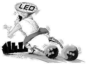 With the deepening of energy conservation and environmental protection and high energy efficiency in various industries around the world, LED is inevitable. Europe and the United States as the world's leading LED application base, its technical level and popularity are ahead of other regions, holds the majority of the LED high-end market. In terms of LED standards, Europe and the United States have also taken precedence over other countries and regions. Highly demanding technologies and safety standards have gradually become technical trade barriers for developed countries. The use of highly demanding technologies and safety standards as technical barriers has the characteristics of high technology, concealment, low transparency, difficulty in supervision, and low versatility, and has gradually replaced traditional trade protection measures such as tariffs, permits, and quotas. Some developed countries rely on their leading scientific and technological advantages and strong economy to formulate technical regulations, safety standards, etc. on the grounds of maintaining basic national security, safeguarding human health and safety, protecting the ecological environment, preventing fraudulent behavior, and ensuring product quality. Commodities have set stringent market access conditions and have created major obstacles to foreign trade in other countries, especially developing countries.
This article will focus on the LED lighting products involved in the safety, electromagnetic compatibility, performance and other aspects of the requirements and standards combing and interpretation, in order to provide a reference for the domestic LED lighting industry.
I. European and American major standards agencies and certification marks
ANSI: The American National Standards Institute is a voluntary organization of companies, governments, and other members. It rarely stipulates standards. ANSI standards are used voluntarily, but standards quoted by law and government agencies are generally Is a mandatory standard.
UL: It is the abbreviation of Underwriter Laboratories Inc. The UL Safety Test Institute is the most authoritative in the United States. It is also a large private institution engaged in safety testing and identification in the world.
FCC: The Federal Communications Commission is an independent agency of the U.S. government and is directly accountable to Congress. The FCC coordinates domestic and international communications by controlling radio broadcasting, television, telecommunications, satellites, and cables.
ETL: ETL is short for Electrical Testing Laboratories. The ETL Laboratory was founded by American inventor Edison in 1896 and enjoys a high reputation in the United States and worldwide. The lower right "us" indicates that it applies to the United States, and the lower left "c" indicates that it applies to Canada, while having "us" and "c" applies to both countries.
EnergyStar: Energy Star, an energy conservation program led by the U.S. government that focuses on consumer electronics, was launched by the US Environmental Protection Agency (EPA) in 1992 to reduce energy consumption and Reduce greenhouse gas emissions from power plants.
IEC: The International Electrotechnical Commission is the world’s first established international electrotechnical standardization agency. It is responsible for the international standardization work in the fields of electrical engineering and electronic engineering. Nearly 100,000 experts from around the world participate in the standardization of IEC standards. Revision work.
ENEC: (EuropeanNormsElectricalCertification, European Standard Electrical Approval) is a generic European standard used for specific and European-compliant products (such as lighting equipment, components, and office & data equipment), the ENEC mark is a universal mark of European safety certification, 2000 The "ENEC" logo, which was originally allowed only by European manufacturers, began to be used by all manufacturers worldwide.
GB: Chinese Pinyin abbreviation for "National Standard", numbered by the code of the national standard, the serial number issued by the national standard, and the year number issued by the national standard (using the last two digits of the year of release), which is compiled by the standardization administrative department of the State Council. Released by the National Standardization Competent Authority to release uniform standards across the country.
CCC: China Compulsory Certification. The compulsory product certification system began on December 3, 2001. The original "CCIB" certification and "Great Wall CCEE certification" were unified as "China Compulsory Certification". Its English abbreviation is " "CCC", abbreviated as "3C" certification, its product catalog contains 19 major categories and 132 kinds of products. The products in the catalog must be certified by a nationally-accredited certification body. After obtaining relevant certificates and applying certification marks, they can leave the factory and import. Sales and use in business services.
Second, the EU market access standard for LED products
Exporting to EU countries requires the adoption of safety certification testing (LVD) and electromagnetic compatibility certification testing (EMC). The main certification marks are CE and ENEC. The certification reference standards mainly include: IEC/EN: 60598-1 (general requirements for luminaires) And tests), IEC/EN: 60598-2-3 (Safety Requirements for Road and Street Lighting Fixtures), IEC/EN62031 (General Safety Requirements for LED Modules) IEC/EN: 61000-3-2 (single-phase input current ≤ 16A Equipment Harmonic Current Emission Limits), IEC/EN: 61000-3-3 (Voltage fluctuations and flicker limits in low-voltage power supply systems), IEC/EN 61547 (Electromagnetic Compatibility Immunity Requirements for General Lighting Equipment), IEC/ EN55015 (Limits and Measurement Methods for Radio Disturbance Characteristics of Electrical Lighting or Type Equipment) CE certification and ENEC certification are basically the same, but there are significant differences in certification. The main performance is as follows:
1.ENEC must be tested and certified by an ENEC member certification body. CE is a self-proclaimed certification. If the company believes that its products have met CE certification standards, it does not require third-party testing and certification. Posted CEmark;
2. ENEC certification, its manufacturer's product management must comply with ISO9002, or its equivalent standards, CE certification does not require ISO-related standards;
3.ENEC certification requires that according to the harmonization inspection procedure, the initial and minimum annual output will be subject to inspection by the issuing authority. CE certification products do not require the inspection of the relevant certification body;
4.ENEC certification requires selective retesting of certified products every other year, and requires retesting costs. CE certified products are continuously effective if the products have not been changed;
5.ENEC adopts the "Standard European Committee for Standardization (EN)" standard and the CE adopts the "International Electrotechnical Commission (IEC)" standard, but the contents of the two standards are exactly the same;
6.ENEC certification, if the power is purchased, the power must pass ENEC certification, and then use the power supply as a lamp for certification testing, if the power supply is the applicant's own production, you can not need ENEC certification, but need to do random testing with the lamp, The reference standard is EN61347-1 (general requirements and safety requirements of the lamp control device), EN61347-2-13 (special requirements for the control of LED modules using AC or DC electronic devices), CE certification power supply if CE certification mark, only The test power supply and the EMC test of the luminaire no longer perform random safety tests on the power supply.
Third, the North American market LED product access standards
The main certifications for exporting to the North American market include UL, ETL, FCC and ENERGY STAR (Energy Star). The LED road lighting products UL certification refers to UL8750 or UL60950, UL1598, and does not test the EMC characteristics of the lamps. ETL certification test quoted It is exactly the same as the UL standard. FCC certification quoted FCCPart15B, ClassAdigitaldevice test limit standards, does not test the safety characteristics of lamps; ENERGYSTAT (EnergyStar) mainly for residential areas and commercial lighting class LED lamps and optical performance requirements, LED road lighting temporarily not listed; here Introduce and analyze the more common UL and FCC certification: The compulsory certification of electronic products in the United States laws and regulations always includes Title1 to Title50. Among them, Title47 is a teletype video product. There are a total of Part0 to Part499, of which Part0 to Part199 are FCC. FCC certification is divided into Verification (self-certification), Declaration of Conformity (announcement declaration) and Certification (certification) three modes, using Verification, there is no test laboratory requirements, can not test (as long as the product can meet the corresponding Technical requirements) and do not need to provide information to the FCC; when using the Declaration of Conformity, test laboratories must obtain NVLAP, A2LA qualification or FCC-certified laboratories, and need multilateral mutual recognition agreements, but do not need to provide information to the FCC; use Certification The test lab is required to register on the FCC website and is officially approved by the FCC. The TCB designated by the FCC or the FCC will issue the certificate, and it will need to provide information to the FCC and obtain an FCC ID. Which authentication method to use depends on the type of product. The standard for FCC testing of LED lighting products is FCC Part15B. The certification type is: Verification.
The FCC is a mandatory certification for the EMI characteristics limits of teletype video products stipulated by the U.S. federal law. The FCC certification test of LED lamps and the EMC certification test in the EU CE are quite different. The main performance is as follows:
1. The FCC certification of LED lamps only tests EMI (radio disturbance) and does not include EMS (radio immunity) test items; in the EMC testing of CE, both require certification testing;
2. The FCC certification of LED lamps and lanterns is divided into Class A (LED lamps used in industrial and commercial environments) and Class B (LED lamps used in residential environments). The test limits of the two types are completely different. The radio in CE certification is not the same. There is only one harassment test limit standard, and the limit value is equivalent to Class B in the FCC;
3, FCC certification of LED lamps Conducted harassment scan test frequency from 0.15MHz to 30MHz end, CE certification of conducted disturbance scan test frequency from 9KHz to 30MH end;
4. The frequency of radiated disturbance scan test of LED luminaires is from 30MHz to 1GHz, and the space radiation harassment scan test frequency in CE certification starts from 30KHz to 300MH.
5, FCC certification requirements are more stringent, the EMI certification test limit standards usually require more than 6dB margin, CE certification EMI test margin at 3dB or more (including the read-point margin) can be;
UL certification in the United States is a non-mandatory certification, mainly for product safety performance testing and certification, and its scope of certification does not include EMC (electromagnetic compatibility) characteristics of the product. The following briefly describes the LED road lighting products involved UL8750, UL1310 and UL60950. The UL8750 is suitable for minimum safety requirements for LED lighting source components that are to be installed in non-hazardous locations rated 600V or lower, and also suitable for minimum safety of LED sources that are connected to isolated (no effectively connected) power sources such as batteries and fuel cells. Requirements; UL1310 is suitable for applications that include input voltages of 120 or 240Vac voltages via software or plug-in connection to a 15 or 20A AC branch circuit or potentially less than 150V ground, using insulated transformers and DC or AC energy sources that can be incorporated into rectifiers and other components It is expected that it can be used to provide energy for low-voltage power-operated CLASS2 power supplies; UL60950 is applicable to safety standards for information technology (IT) equipment, including mobile phones, computers and peripherals such as projectors, printers, etc. Including output power supply with LPS (Limited Power Supply) safety loop;
In the UL certification of LED lighting products, UL1310 or UL60950 can be used to test the driver power supply. The main differences between the two standards are as follows:
1. UL1310 is a CLASS II (power supply with limited voltage and capacity) power supply equipment safety standards. When the UL1310-certified power supply is a CLASS II power supply, and CLASSII power supply is used as a cUL (Canada market) LED lighting fixture certification, relevant safety tests can be exempted. UL60950 is a safety standard for information technology (IT) equipment, and its applicable certification scope is greater than UL1310, but when using a UL60950-certified power source for cUL (Canadian market certification) LED lighting fixture certification, safety testing cannot be exempted. ;
2. The UL1310 standard stipulates that the maximum output voltage (including no load) of the output voltage at the output voltage under any load condition is 42.4V. When the device does not contain the maximum output volt-ampere, the output voltage of the power-off device in the output circuit is not more than 100 volt-ampere; UL60950 defines the voltage between any two accessible circuit components under normal output voltage conditions, or the voltage between any accessible circuit component and the protective earth terminal of a Class I device, not exceeding 42.4V AC peak, or 60V DC
3, UL1310 certification applies only to 120 or 240Vac calibration voltage in the power grid CLASSII power supply equipment, UL60950 for rated input voltage does not exceed 600Vac of information technology products, for 277V voltage system UL certification of LED lighting products, power supply, can only Reference UL60950 standard certification test.
Fourth, the domestic market LED products related standards and certification
The domestic sales of LED products mainly include two types of CQC mark certification and CCC mandatory certification, testing and certification by the China Quality Certification Center (CQC). LED road lighting products domestic CCC mandatory certification reference standards are GB7000.1-2007 (general safety requirements and test lamps), GB7000.5-2005 (road and street lighting safety requirements), GB17625.1-2003 (per Phase input current ≤16A EMC limits of equipment harmonic current emission limit), GB17743-2007 (Limits and methods of measurement of radio disturbance characteristics of electrical lighting and similar equipment), GB/T18595-2001 (General lighting equipment Electromagnetic Compatibility Immunity Requirements), its standard content and test methods are basically the same as IEC standards; the CQC mark certification of LED lighting products is mainly the certification of energy-saving standards, which was issued and implemented by the China Quality Certification Center in December 2010, LED roads. The reference standard for CQC energy-saving mark certification of lighting products is CQC31-465392-2010 (LED road/tunnel lighting energy-saving certification rules), and its standard content makes stringent requirements for the indicators of the photoelectric parameters of LED road lighting products. The initial light efficiency, luminous flux maintenance rate, initial correlated color temperature and other indicators are much higher than local standards. At present, there are very few companies that have passed LED lighting certification. Series of energy-saving products have passed the CQC logo certification. The following describes the differences between CQC mark certification and CCC mandatory certification:
1. The CQC mark certification is voluntary certification in China and is not enforced in the product countries within the scope of CQC mark certification. The products with the CQC mark indicate that the product meets the requirements for quality, safety, environmental protection, performance, and organic agricultural products; CCC certification is a mandatory certification in China. All products in the CCC-certified product catalog must have CCC certification for sales in mainland China. Otherwise, they are illegal products that cannot be shipped, imported, sold, or used.
2. The range of products covered by the CQC mark certification is greater than the CCC compulsory certification. The certification scope of the CQC mark involves more than 500 products. The CCC mandatory certification product directory contains 19 categories and 132 products. For example, the CCC mandatory certification catalogue is not Including LED road lighting products, do not need to do CCC certification, but can do CQC energy-saving logo certification, LED downlights and other indoor use products in the CCC mandatory certification product catalog, in addition to mandatory CCC certification can also be done CQC energy-saving mark certification;
3, CCC mandatory certification is safety and electromagnetic compatibility mandatory safety certification, not the product of the photoelectric parameters and product quality indicators for certification testing, CQC mark certification products meet the quality, safety, environmental protection, performance and other standard requirements, involving Optoelectronic parameters and product quality indicators, etc. need to be tested;
4. To apply for CQC mark certification, if the product is within the scope of the CCC mandatory certification catalogue, it must first pass the CCC certification. Products that are not within the scope of CCC must first pass national or industry-specific safety and electromagnetic compatibility safety standard tests.
High Frequency PCB - Definition, Characteristics, Manufacturing, Materials and Application Scenarios
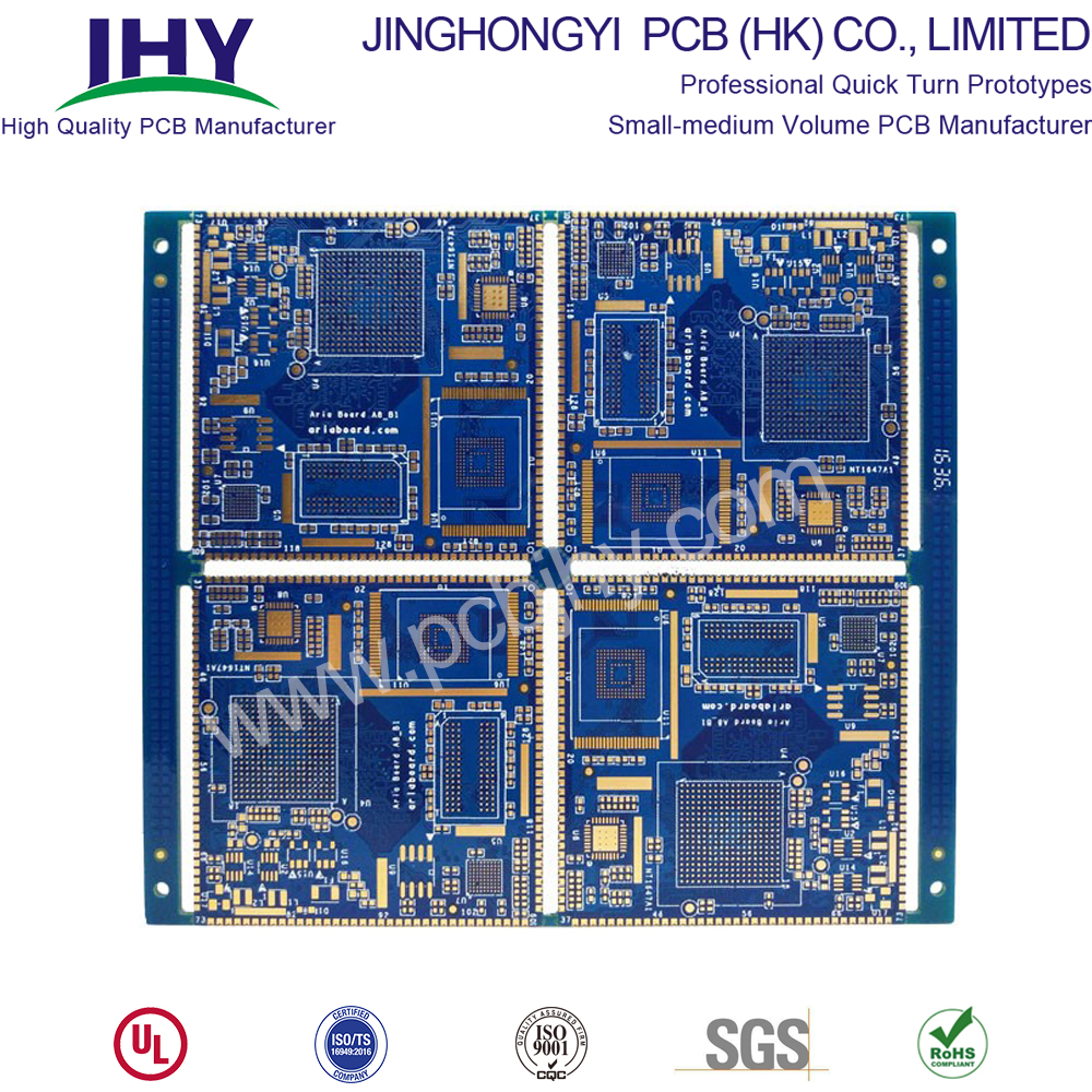
What Is A High Frequency Circuit Board?
High frequency circuit board (HF PCB) is a special circuit board with high electromagnetic frequency. Generally speaking, high frequencies can be defined as frequencies above 1GHz. Its physical performance, accuracy and technical parameters are very demanding. It is often used in automobile anti-collision system, satellite system, radio system and other fields.
High Frequency PCB include:
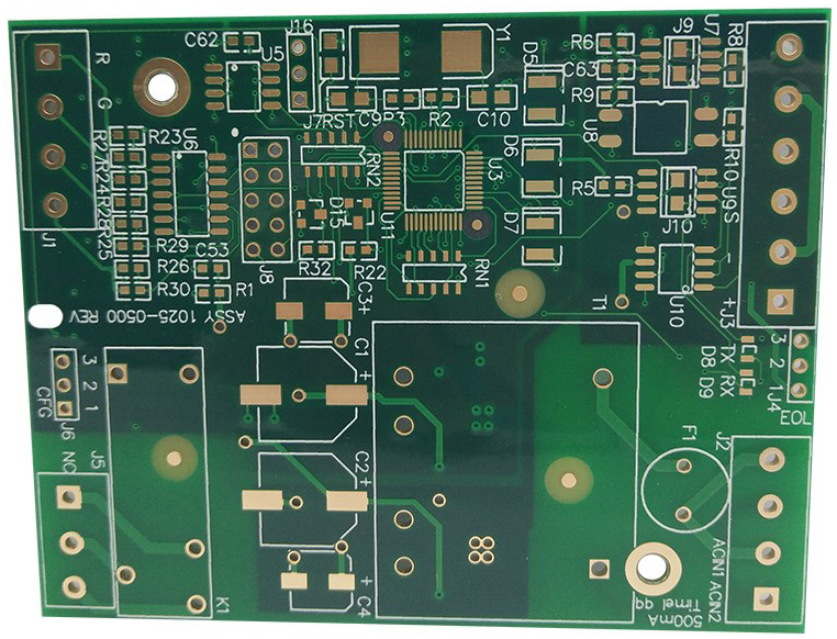
The utility model patented high frequency circuit board includes a core board with a hollow groove and a copper clad plate adhering to the surface and the lower surface of the core board by flow glue. The upper opening and the lower opening edges of the hollow groove are provided with a baffle.
The high frequency circuit board provided by the utility model is provided with a barrier which can block the flow glue at the upper and lower edges of the hollow groove of the core board.
In this way, the flow glue will not enter the hollow slot when the core plate is bonded with the copper clad laminate placed on the upper and lower surfaces, that is, the bonding operation can be completed by one press.
Compared with the existing technology, the high frequency circuit board can only be completed by secondary pressing. The high frequency circuit board in the utility model has the advantages of simple structure, low cost and easy manufacture.
Characteristics of High Frequency Circuit Board
Generally speaking, high frequency circuit boards have their own characteristics: low dielectric constant, relatively stable. In theory, the smaller the dielectric constant, the more stable the signal, and the higher the frequency circuit board can play a better role in signal transmission. Medium loss is very small, it is not easy to absorb water and moisture, heat resistance, corrosion resistance and other excellent performance. Conversely, if the dielectric constant is high, the signal transmission process is slow.
The thermal expansion coefficients of high frequency circuit boards and copper foil are also correlated to a certain extent. They are consistent as far as possible. The inconsistency can easily lead to the separation of copper foil in the alternate change of heat and cold. The later use will affect the signal transmission of PCB. The absorbency of high frequency circuit board is lower than that of other multi-layer circuit boards, because humidity will affect the dielectric constant and dielectric loss of high frequency circuit board. In addition, the heat resistance, chemical resistance, impact strength, peeling strength and other requirements are also good.
High frequency signals are vulnerable to noise and come with much tighter impedance tolerance as compared to conventional circuit boards.
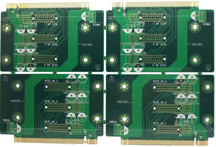
High Frequency Circuit Board Materials
Therefore, when selecting a substrate for a PCB for a high-frequency circuit, it is particularly necessary to examine the various characteristics of the material DK at different frequencies. For the requirements of high-speed transmission of signal emphasis, or characteristic impedance control requirements, focus on DF and its performance under conditions of frequency, temperature and humidity.
Under the condition of frequency change, the general type of substrate material shows a large change of DK and DF values. Especially in the frequency range of l MHz to l GHz, their DK and DF values change more significantly. For example, a general-type epoxy resin-glass fiber-based substrate material (general type FR-4) has a DK value of 4.7 at a frequency of 1 MHz, and a DK value of 4.19 at a frequency of 1 GHz. Above lGHz, its DK value tends to be flat. The changing trend is smaller as the frequency increases (but the change is not large). For example, at 10 GHz, the DK value of FR-4 is generally 4.15, and the substrate material having high-speed and high-frequency characteristics changes in frequency. In the case of DK, the DK value changes little, and the DK keeps changing in the range of 0.02 from the frequency of change from 1 MHz to 1 GHz. Its DK value tends to decrease slightly from low to high frequency.
The dielectric loss factor (DF) of a general type of substrate material is affected by a change in frequency (especially in a high-frequency range), and the change in DF value is larger than that of DK. The law of change tends to increase. Therefore, when evaluating the high-frequency characteristics of substrate material, the focus of its investigation is on the change of its DF value. There are two distinct types of two types of substrate materials with high-speed and high-frequency characteristics. In general, there are two different types of substrate materials: one is that the (DF) value changes little with frequency. There is also a class that, although similar in magnitude to the general substrate material, has a lower (DF) value.
High-frequency circuit boards with induction heating technology have been widely used in the communication industry, network technology field promotion and high-speed information processing systems to meet the requirements of many high-precision parameter instruments. A reliable high-frequency circuit board provides great help in actual production.
The circuit board material with DF between 0.01 and 0.005 is suitable for the digital circuit with the upper limit of 10Gb / S;
DF between 0.005-0.003 is suitable for digital circuits with an upper limit of 25gb / s;
Circuit board materials with DF no more than 0.0015 are suitable for 50GB / s or even higher speed digital circuits.
Common high-speed PCB materials are:
1) Rogers: ro4003, ro3003, ro4350, ro5880, etc
2) TUC: tuc862, 872slk, 883, 933, etc
3) Panasonic:Megtron4.Megtron6, etc
4) Isola: fr408hr, is620, is680, etc
5) Nelco:N4000-13.N4000-13EPSI, etc
6) ShengYi
Of course, there are many other high-frequency board materials, such as Arlon (acquired by Rogers) and Taconic, which are all old brand RF microwave material factories with guaranteed performance.
Our most common request is for FR-4 material, which is composed of woven fiberglass bound by an epoxy resin, and which we always keep stocked as one of our PCB Options at a Standard Price. FR-4 is a robust material with excellent thermal characteristics, and electrically it is known to perform quite reasonably at RF or Microwave frequency levels.
Some clients whose designs are intended for particularly demanding applications-such as high-power or broadband circuits-find that FR-4 sometimes just does not do the job at those higher frequencies. In these cases, we are always happy to help you find a laminate material to suit your specific needs, and our highly customizable PCB Assembly Process can be easily adjusted to make sure your project lead time is not impacted.
A snapshot of the datasheet for FR-4 material is shown below for reference.
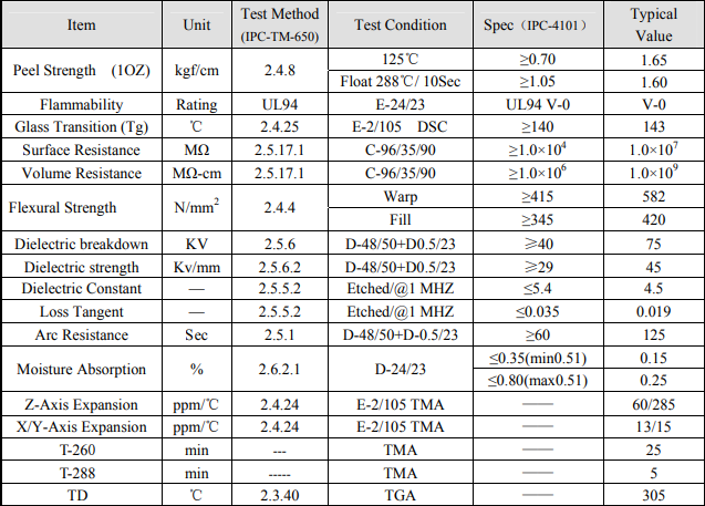
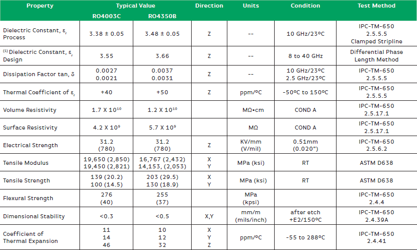
The most popular high-frequency-specific laminate materials were developed by Rogers, and referred to with an [RO-[ prefix. These high-quality materials exhibit approximately a 20% reduction in dielectric constant, compared to standard FR-4; they also boast rather impressive thermal characteristics, with Tg values above 280°C . A snapshot of the datasheet for RO4350B and RO4003C is included below for your convenience.
Requirements for Manufacturing Materials of High Frequency PCB
1. Dielectric loss (Df) must be small, which mainly affects the quality of signal transmission. The smaller the dielectric loss, the smaller the signal loss.
2. Low water absorption. High water absorption will affect dielectric constant and dielectric loss when damped.
3. The dielectric constant (DK) must be small and stable. Usually the smaller the better. The transmission rate of the signal is inversely proportional to the square root of the dielectric constant of the material. High dielectric constant easily causes signal transmission delay.
4. The coefficient of thermal expansion of copper foil is the same as that of copper foil, because the inconsistency will cause the separation of copper foil in the change of cold and heat.
5. Other heat resistance, chemical resistance, impact strength and peeling strength must also be good.
How to choose high frequency high speed PCB material
To select the PCB substrate, a balance must be made among meeting the design requirements, mass production and cost. In short, the design requirements include electrical and structural reliability. Generally, when designing a very high-speed PCB Board (frequency greater than GHz), PCB material problem will be more important. For example, the FR-4 material, which is commonly used now, has a large dielectric loss DF (dielectric loss) at several GHz, which may not be applicable.
For example, 10Gb / s high-speed digital signal is a square wave, which can be regarded as the superposition of sine wave signals of different frequencies. Therefore, 10Gb / s contains many different frequency signals: 5GHz fundamental signal, 3-order 15GHz, 5-order 25ghz, 7-order 35GHz signal, etc. The integrity of the digital signal and the steepness of the upper and lower edge are the same as the low loss and low distortion transmission of the RF microwave (the high-frequency harmonic part of the digital signal reaches the microwave frequency band). Therefore, in many aspects, the selection of high-speed digital circuit materials is similar to the requirements of RF microwave circuits.
The main factors to be considered in the selection of suitable base materials are as follows:
1. Manufacturability:
2. Various performances (electrical, performance stability, etc.) matching with products:
Low loss, stable Dk/Df parameters, low dispersion, small variation coefficient with frequency and environment, small tolerance of material thickness and glue content (good impedance control), if the trace is long, consider low roughness copper foil. In addition, the high-speed circuit needs to be simulated in the early stage of design, and the simulation result is the reference standard of the design. "Xingsen Technology-Agilent (High Speed/RF) Joint Lab" solves the performance problems of inconsistent simulation results and tests. It has done a lot of simulation and actual test closed-loop verification, and the simulation can be consistent with the actual measurement through unique methods.
3. The availability of materials in a timely manner:
Many high-frequency board material procurement cycles are very long, even 2-3 months; in addition to the conventional high-frequency board material RO4350 in stock, many high-frequency boards material need to be provided by customers. Therefore, high-frequency plates need to communicate with manufacturers in advance, and prepare materials as soon as possible;
4. Cost:
5. Applicability of laws and regulations:
It should be integrated with environmental protection regulations of different countries to meet the requirements of RoHS and halogen-free.
Among the above factors, the high-speed digital circuit operation speed is the main factor to be considered in PCB material selection. The higher the speed of the circuit, the smaller the DF value of the selected PCB material. The low loss circuit board will be suitable for 10Gb / s digital circuit; 25gb / s digital circuit needs to select the board with lower loss; ultra-low loss board will be suitable for the faster high-speed digital circuits, and its speed can be 50GB / s or higher.
How to Make High Frequency Circuit Board?
Fabrication Principle of High Frequency Circuit Board
In the design of high frequency circuit, the power supply is designed in the form of layers, which is much better than that in the form of buses in most cases, so that the circuit can always follow the path with the smallest impedance. In addition, the power board has to provide a signal loop for all generated and received signals on PCB, which can minimize the signal loop and reduce noise, which is often ignored by low frequency circuit designers.
In the design of high frequency PCB, we should follow the following principles:
Points for Attention in Manufacturing High Frequency Circuit Board
1. Impedance control is strict, relative line width control is very strict, general tolerance is about 2%.
2. Because of the special plate, the adhesion of PTH copper deposit is not high. Usually, plasma treatment equipment is needed to roughen the through-hole and surface to increase the adhesion of PTH copper and solder resist ink.
3. Do not grind the plate before welding resistance, otherwise the adhesion will be very poor, and can only be coarsened with micro-corrosive powder.
4. Most of the sheets are PTFE materials. There will be many rough edges when they are formed by ordinary milling cutters, which need special milling cutters.
5. High frequency circuit board is a special circuit board with high electromagnetic frequency. Generally speaking, high frequency can be defined as frequency above 1 GHz.
Its physical performance, accuracy and technical parameters are very demanding. It is often used in automobile anti-collision system, satellite system, radio system and other fields.
Scenario and Field of High Frequency Circuit Board Application:
Nowadays, the high frequency of electronic equipment has become a trend of development, especially in the growing development of communication networks, aerospace, military equipment, intelligent transportation, information products are also increasingly high-speed and high-frequency. Nowadays, with the development of science and economy, many new products need high frequency circuit boards. High frequency circuit boards play an increasingly important role in people's daily life.
It is not easy to find a fast and good manufacturer of high frequency circuit boards. Jinghongyi PCB has its own unique board advantages in making high frequency circuit boards. It has reliable automatic production equipment and testing equipment.
Reasons for Choosing Jinghongyi PCB
1. Top imported raw materials for high frequency circuit boards to ensure product quality from the source
2. Full set of surface treatment equipment to meet the needs of various industries
We are one of the few companies in PCB industry equipped with complete surface treatment equipment.We can deal with the Immersion Gold completely.
Immersion Silver, Immersion tin, OSP, tin spraying, gold plating, thick gold plating, tin plating, silver plating and other related requirements.
3. Leading PCB Multilayer Circuit Board Technology Capability
4. Strict PCB quality control system to effectively guarantee product performance
5. Top Technical Team
Eight years of focus on R&D and manufacture of high-frequency board and microwave radar RF circuit board, with a dedicated, united and tenacious R&D team, customers NPI stage products, all into the process evaluation system, meet the evaluation criteria of the project, further review by the R&D team and file a case tracking the whole process.
The staff has 3-12 years of professional and technical personnel with multi-layer circuit board experience. They have rich experience in various industry standards and process quality requirements.
6. Intimate service
Service concept: regard customers as eternal partners, develop together, only choose reputation, not customers, regardless of the size of customers, in the case of customer needs, to provide the best service.
Flexible service: We will be eager to meet the customers'needs, think what they want, and do our best to help customers solve problems, reduce losses or promote project development.
Useful Resources