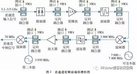
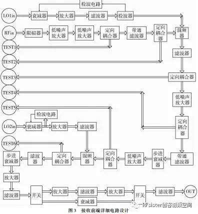
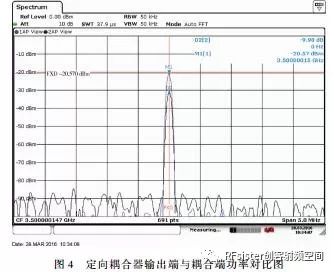
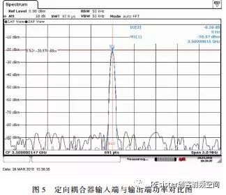
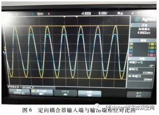
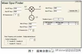
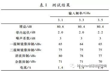
The performance of the radar system is seriously affected under the combined action of complex electromagnetic signals such as radar signals, radar jamming signals, multipath signals, and clutter signals. In order to clarify the influence mechanism and law of action between the input signal and output phenomenon of the radar system, the research on the front-end technology of the radar system with radio frequency monitoring capability was carried out. Based on the CPCI bus architecture, the receiving front end uses multiple modes of signal coupling and sampling methods to extract signals from each key node in the radar system receiving front-end channel, which is the multi-path coupling effect of the radar signal receiving channel and the multi-element superimposition effect of the complex electromagnetic environment. The mechanism research provides a basic test platform and measurement data. introduction The complex electromagnetic environment is one of the most prominent features of modern and future battlefields. As electronic information equipment, the detection capability of radar systems is severely restricted by the electromagnetic environment [1]. The performance research of current radar systems under the effects of complex electromagnetic environment is mainly carried out based on the radar countermeasure effect evaluation system. This type of system is not only expensive, but also the hardware conditions of the system have been solidified and packaged, and there are no reservations and leads specifically for complex electromagnetic environment effects. The intermediate test port of the research can only analyze the interference phenomenon with the final display result of the actual radar. This analysis is feasible for the effect of a single interference source on the radar. However, when multi-source interference or complex electromagnetic environment elements increase At this time, it is very difficult to analyze the influence of the complex electromagnetic environment on the radar system only through the final result [2]. Therefore, it is very important to study and establish evaluation platforms and test methods for radar detection capabilities in complex electromagnetic environments. The purpose of this paper is to design and study a radar receiving front end with radio frequency monitoring port, which realizes signal monitoring at key signal flow links in the receiving channel, and provides hardware foundation and necessary data support for the study of the mechanism of multi-element superimposition effects in the electromagnetic environment. 1 working principle The receiver adopts the single pulse angle measurement method commonly used in high-precision measurement radar systems. The monopulse angle measuring radar needs to take into account the two systems of amplitude ratio and phase ratio at the same time. Under the amplitude ratio system, the radio frequency front end of the radar receiver has two receiving branches, the sum channel and the difference channel. Under the phase comparison system, there are two channels in the coordinate plane. Therefore, the receiving front end is designed as a dual-channel link structure based on the CPCI bus architecture, forming two receiving branches, sum and difference, which are used to receive the sum branch signal and the difference branch signal respectively. The receiving front end adopts a superheterodyne variable frequency link, which is mainly composed of limiter, low noise amplifier, mixer, mid amplifier, filter, local oscillator, etc. At the same time, couplers are used before and after each key component module to lead to radio frequency monitoring points. The radar receiving front end converts the target echo signal with a frequency range of 3.1 GHz to 3.5 GHz and a power range of -100 dBm to -30 dBm to a 70 MHz intermediate frequency through a superheterodyne frequency conversion link, and the maximum output power of the intermediate frequency is 0 dBm. The block diagram of the receiving front-end principle is shown in Figure 1 and Figure 2. 2 System design 2.1 System indicator requirements Key technical indicators of receiving front-end: Receiving frequency range: 3.1 GHz~3.5 GHz; Radar signal bandwidth: 1 MHz, 2.5 MHz, 5 MHz optional; Noise figure: ≤3 dB; Receiving sensitivity: -100 dBm; Receiving dynamic range: -100 dBm~-30 dBm; Receive channel gain: better than 70 dB; Intermediate frequency: 70 MHz, bandwidth 5 MHz; Output IF level: ≥0 dBm; In-band fluctuation: ≤3 dB; Image rejection: ≥60 dBc; Harmonic suppression: ≥30 dBc; Spurious suppression: ≥50 dBc. 2.2 Circuit design The receiving front end mainly includes a sum channel and a difference channel, and the two channels use the same design link. Because the superheterodyne receiver has the characteristics of low spurious and high image rejection, the design adopts the double conversion scheme of the superheterodyne receiver, and selects a high intermediate frequency to reduce the influence of mixing interference on the target signal. The design mixes the target echo signal with an input frequency range of 3.1 GHz~3.5 GHz and a power range of -100 dBm~-30 dBm with a variable local oscillator signal with a frequency range of 7 GHz~7.4 GHz, and the output frequency is 3.9 GHz The first intermediate frequency signal is mixed with a fixed local oscillator with a frequency of 3.97 GHz to output an intermediate frequency signal with a frequency of 70 MHz. The signal is sent to the intermediate frequency acquisition module for subsequent sampling and demodulation. According to the sensitivity, output signal-to-noise ratio, and output intermediate frequency level, the receiver gain is calculated to be 80 dB, and the specific gain is allocated to the RF low-noise amplifier and the first intermediate frequency and the second intermediate frequency amplifier. The detailed circuit design is shown as in Fig. 3. 3 Design and analysis of key technical indicators 3.1 Influence analysis of directional coupler The radio frequency monitoring interface is a non-functional port of the radar receiving front end, so the design of this interface will not affect the radio frequency channel functionally, and at the same time can achieve the purpose of leading out the monitoring points and monitoring the signals of the key nodes of the radio frequency channel. Through the analysis of the signal derived from the monitoring interface, the key parameters such as the frequency and power of the main channel signal in the radio frequency channel at the node can be obtained. In this design, a directional coupler is used to lead out the monitoring point to the radio frequency channel. Because the insertion loss of the directional coupler affects the sensitivity of the receiver, if the directional coupler with an insertion loss of 0.3 dB is placed in the front stage of the low noise amplifier, the receiver sensitivity will be reduced by about 0.3 dB. Because the signal has been amplified, the directional coupler connected after this node no longer affects the sensitivity of the receiver. In order to avoid the influence of multiple couplers on the sensitivity of the system at the same time, the design adopts the method of power compensation to adjust the influence of the coupler. There are two methods of power compensation, one is step-by-step power compensation, that is, the power of this point is adjusted before the coupler in the process, and the gain is amplified first, and then the coupler is added; the other is in all couplings. Add a low-noise amplifier to the final output of the converter to perform the final one-time power compensation on the module. The step-by-step power compensation method causes the instability of the system power due to its repeated amplification and attenuation, which changes greatly with the change of the ambient temperature. From the performance analysis, repeated amplification and attenuation will increase the stray power, which will affect the system's indicators. Finally, the one-time power compensation method can effectively adjust the power of the system power attenuation caused by the insertion loss of the coupler, so as to minimize the spurious influence of the system. In addition, the receiving module is controlled by gain, and the output power is controlled above -60 dBm, so there will be no small signal output, and the impact of a single power adjustment on the system can be ignored. After the above considerations, a single power amplification method is finally used to compensate for the influence of coupling on the power. The total insertion loss of the multi-stage directional coupler is not more than 6 dB, and the receiving front end can compensate the insertion loss of the multi-stage directional coupler through the amplifier, so the multi-stage directional coupler has little effect on the output power of the rear stage of the receiving front end. In order to study the influence of the coupler on the system, the power and phase tests of the directional coupler were carried out. The input frequency of the coupler is a continuous signal with a frequency of 3.5 GHz and a power of -20 dBm. The output signal power at the coupling end is -9.98 dBm, and the signal power measured at the output end of the coupler is -20.57 dBm. The test result shows that the attenuation value of adding a coupler to the main signal is less than 0.6 dB. The test results are shown in Figure 4 to Figure 6. Through the above power and phase tests, we can see that in the 3.1 GHz ~ 3.5 GHz frequency band, the addition of couplers will not have any effect on the phase of the main circuit signal, and the addition of a single coupler will produce no more than 0.5 dB on the main circuit. The insertion loss. Through power compensation, the change of main circuit power will not be affected. 3.2 Gain distribution design Because the receiver has a large dynamic range and requires high sensitivity, it is necessary to allocate the gain in the receiving channel, and allocate it to the RF low-noise amplifier, the first intermediate frequency with a frequency of 3.9 GHz and the second intermediate frequency with a frequency of 70 MHz. . The insertion loss of the limiter used in the design of the receiving front-end channel is 1 dB, the gain of the low-noise amplifier is 30 dB, and the insertion loss of the mixer is 8 dB. The intermediate frequency amplifier group uses automatic gain control amplifiers, as shown in Figure 3 The circuit design diagram shows that the total channel gain is about 85 dB, which meets the design index requirements. At the same time, in order to ensure that the local oscillator power of the mixer is within a reasonable range, a detection circuit is designed during the frequency conversion process of the receiving front end. During the frequency conversion process, the detector will sample and detect the power of the input signal, and the detected level value reflects the power of the sampling point. At the same time, the analog-to-digital converter in the detection circuit performs data sampling on the level value, and Real-time control of the attenuator, so as to realize the automatic control of the output power. 3.3 Mixing spurious design The radar receiving front end adopts a superheterodyne receiver frequency conversion method. The radar target signal is down-converted to an intermediate frequency signal through two frequency conversions. The first mixing outputs a fixed frequency intermediate frequency signal of 3.7 GHz. This signal is filtered by a narrowband filter and fixed The local oscillator signal with a frequency of 3.97 GHz is mixed for the second time, and an intermediate frequency signal with a frequency of 70 MHz is obtained by mixing, and the intermediate frequency signal is output through narrowband filtering. Therefore, the mixing spurs are mainly caused by the first mixing, and the first mixing spurs of the receiving front end are simulated and calculated by the mixing spur calculation software. In the calculation, the input signal frequency range is 3.1 GHz~3.5 GHz, the input signal harmonic calculation frequency is 3 times, the local oscillator signal frequency range is 7 GHz~7.4 GHz, the local oscillator signal harmonic calculation frequency is 3 times, and the output mixing frequency is calculated Stray. It can be seen from the calculation result of mixing spurious shown in Figure 7 that the 5th spurious suppression in the design is greater than 65 dB, which meets the design index requirements. 4 Performance test results and analysis The technical indicators reached by the designed and developed radar receiving front-end are shown in Table 1. The frequency range of the input test signal is 3.1 GHz~3.5 GHz, the power range is -100 dBm~10 dBm, the frequency range of the first local oscillator signal is 7 GHz~7.4 GHz, the power range is -10 dBm~10 dBm, the second one The frequency of the vibration signal is 3.97 GHz, and the power range is -10 dBm to 10 dBm. It can be seen from Table 1 that the test results of the radar receiving front end meet the design requirements. At the same time, the receiving front end is designed with directional couplers before and after the low-noise amplifier and mixer of the frequency conversion link for radio frequency monitoring. A total of 6 radio frequency monitoring ports are designed for external equipment to measure and analyze. 5 Conclusion This paper proposes a radar receiving front-end technology with radio frequency monitoring capabilities, which solves the problem that existing radars and radar test systems cannot effectively analyze and measure the effects of complex electromagnetic environments during the receiving process. This technology is used to test the single channel characteristics of the receiver and the characteristics between channels under the electromagnetic environment of multiple interference sources and multiple elements. The test results can be used for reference and analysis by radar system designers and debuggers, in order to improve the overall radar system Performance provides the necessary testing methods [3]. At the same time, the receiving front end is based on the CPCI bus architecture, with small size, convenient operation and control, and easy to improve and secondary development. references [1] Hu Jin. Quantitative description of radar detection capability in complex electromagnetic environment[J]. Aerospace Electronic Warfare, 2017, 33(1):32-35. [2] Wang Peizhang, Shao Wei, Yu Tongbin, et al. Research on the front-end technology of broadband integrated reception[J]. Journal of Microwaves, 2012 (8):319-321. [3] Meng Yan, Zhang Linrang, Peng Weijie. Design and implementation of radar multi-channel receiver test system[J]. Electronic Science and Technology, 2017,30(10):5-7,11. Aerial bundled cable is a type of electrical cable that is used for overhead power distribution. It consists of several insulated conductors that are bundled together and covered by a protective sheath. The conductors are usually made of aluminum or copper and are insulated with cross-linked polyethylene or polyvinyl chloride . Aerial Bundled Cable,ABC aerial bundled cable,Aerial Bundled Electrical Cable,Spacer Overhead Insulated line Aluminum cable Ruitian Cable CO.,LTD. , https://www.hbruitiancable.com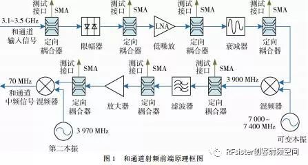
ABC is commonly used in rural areas and in locations where underground cabling is not feasible or cost-effective. It is also used in urban areas for low voltage distribution and street lighting. ABC is designed to withstand extreme weather conditions, such as high winds, snow, and ice.
One of the main advantages of ABC is that it requires less maintenance than traditional overhead lines. The insulated conductors are less likely to come into contact with each other or with trees and other objects, reducing the risk of power outages and other issues.
ABC also offers improved safety compared to traditional overhead lines. The insulation on the conductors reduces the risk of electrical shock and fire, and the bundled design reduces the risk of accidental contact with the wires.
Overall, ABC is a reliable and cost-effective solution for overhead power distribution, particularly in areas where underground cabling is not feasible.