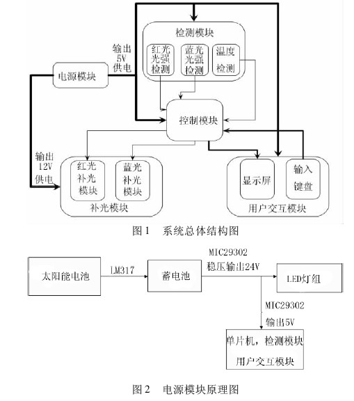
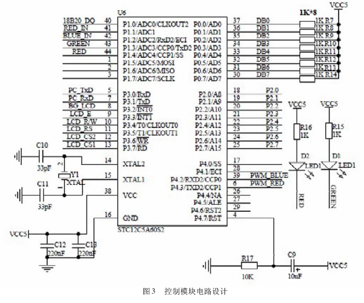
In the process of crop growth, light conditions have an important impact on the growth rate, yield and quality of crops [1, 2]. At present, most of China's facility agriculture still relies on incandescent lamps, tungsten halogen lamps, high-pressure mercury fluorescent lamps, high-pressure sodium lamps, etc. as light sources to supplement the plants [3 - 4]. These traditional methods of complementing light have poor spectral matching [5] - 6], the light energy utilization rate is low, and the influence of other environmental factors is not considered. The high energy consumption makes it difficult to form a high input-output ratio in actual production. With the development of semiconductor technology, the use of LED cold light source as the light source of the fill light has also been proposed [7], which can solve the problem of the above-mentioned fill light source to a certain extent. However, most of the R&D programs and products still use the fixed light intensity and fixed light quality supplement method. The difference in light quantity at different stages of different plants is not considered, resulting in insufficient light filling and excessive light filling. Solve the problem of low energy consumption and precise fill light [8]. In view of the above problems, this paper developed an intelligent, accurate and energy-saving fill light system, which fully considers the influence of different plants on the light requirement of different light in different stages. Based on modern electronic information technology such as sub-band light intensity detection technology and intelligent control technology, STC12C5A60S2 single-chip microcomputer is used as the core processor [9], and PT4115 is the LED driver module [10]. According to the temperature and light intensity detection results, various plants are realized. Quantify the fill light as needed in a suitable environment. Under the premise of meeting the illumination required for growth, the utilization of the output light energy is maximized, and the characteristics are low error, fast response, low cost and simple maintenance. 1 system overall design The system adopts modular design and is divided into power module, detection module, control module, fill light module and user interaction module. The overall structure is as follows. Figure 1 shows. Among them, the power module is powered by solar energy, and provides 5V and 1 2V power supply voltages respectively to supply power to the whole system. The intelligent control mode is applied to the STC series single-chip microcomputer as the core. According to the data collected by the system and the threshold is set, the corresponding PWM control signal is realized. Duty cycle calculation and two-way PWM control signal output; detection module detects red and blue light intensity and real-time temperature in sub-band, and filters and amplifies the detection signal and sends it to the single-chip microcomputer to realize the detection of relevant environmental information; The constant current driving circuit with PWM current control function controls the brightness of the red and blue LED fill light array lights respectively, thereby realizing quantitative accurate fill light; the user interaction module uses the liquid crystal screen to complete the detection result display, and the keyboard realizes the on-demand threshold modification. Such functions, complete the threshold modification and setting, effectively improve the convenience and scalability of the system. 2 hardware design 2. 1 power module The power module of the system consists of solar panels, batteries and control circuits. The whole system is powered by solar cells. The schematic diagram is shown in Figure 2. The input end of the control circuit is connected to the solar cell, and the input voltage is charged to the 12V battery through the LM317 and its peripheral standard circuits, and the battery supplies power to the entire system. The battery output uses the MIC29302 voltage regulator module to output a 12V regulated power supply signal, and adjusts the matching resistor to generate a 5V regulated power supply signal, thus providing the system with two power supplies of 12V and 5V. Among them, the single-chip microcomputer, the detection module and the user interaction module are all powered by a 5V power supply, and the LED fill light module is powered by a 12V power supply. 2. 2 control module The control module selects STC12C5A60S2 as the core processor and uses 5V power supply. It has 8 10-bit A/D interfaces, 2 PWM output ports, 56K flash memory space, 1280 280B static access memory, and 1K programmable read-only memory. Complete node task scheduling, data acquisition, intelligent management, control signal output, threshold adjustment, data dumping, etc. The circuit is shown in Figure 3. The P0 port is connected to the 8 data ports of the LCD screen; the P1 port is responsible for connecting with the sampling signal, the P1. 0 is connected to the temperature detection signal, the P1. 1 is connected to the red light detection signal, and the P1. 2 is connected to the blue detection signal, thereby Complete the collection of sensor monitoring data; P2 port is connected to 4 × 4 matrix keyboard, P3. 0, P3. 1 is used for data read and write line connected to single chip and serial port, complete the download of the program; P3. 2 ~ P3.7 bit LCD The control terminal; P4. 2, P4. 3 is the output port of the PWM control terminal of the single chip microcomputer, which calculates the duty ratio of the PWM signal corresponding to the required light amount of the two bands according to the single chip microcomputer, and outputs the PWM signal to control the brightness of the LED light group. 

LED-based facility agricultural intelligent fill light system
introduction