Overview: 165W Medical Power Supply,165W Medical Device Power Supply,165W Medical Power Adapter,165W Rade Power Supplies Shenzhen Longxc Power Supply Co., Ltd , https://www.longxcpower.com
With the development of modern technology, inverter power is widely used in various industries, and higher requirements are put forward for its performance. The traditional inverter power supply is mostly a control system combining analog control or digital. The good inverter power supply voltage output waveform mainly includes high steady state precision and good dynamic performance. At present, the structure and control of the inverter can obtain a good sinusoidal output voltage waveform, but the effect is not ideal for a waveform with a relatively fast mutation.
The function signal generator is a commonly used device in experimental teaching. Waveforms that can produce different frequencies and voltage levels: square wave signals, triangular waves, sinusoidal signal waveforms. A new DDS technology that has emerged in recent years is the direct digital frequency synthesis technology. But they are all small signal waves, no power output, and can not carry a certain load.
The multi-function inverter power supply proposed in this paper adopts a double-phase single-phase full-bridge inverter structure. The output voltage waveform tracks the given reference waveform and has power output, which can carry a certain load. The control adopts the hysteresis control added to the differential link to fully realize the digital control.
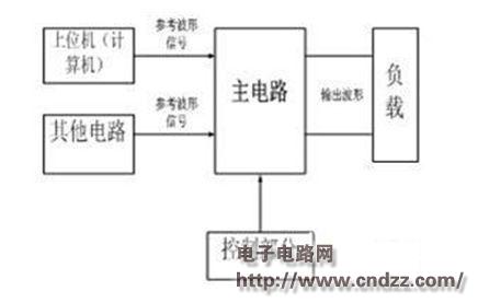
Main Circuit Design The principle of multi-function inverter power supply is shown in Figure 1. It consists of two parts: the main circuit and the control part. The reference signal of the main circuit can be obtained by communication with a computer or other circuits. 
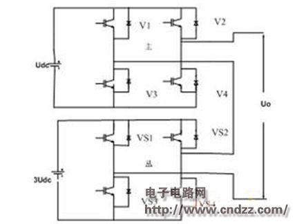
Figure 1: Multi-function inverter power supply principle The multi-inverter structure is borrowed from the design of the main circuit, and a double-phase single-phase full-bridge inverter connection is adopted. The schematic diagram is shown in Figure 2. The DC side voltages of the two inverters are different. The DC side voltage of the main inverter is Udc, and the DC side voltage of the inverter is 3Udc. The transmission voltage waveform has 9 levels: ± 4Udc, ±3Udc, ±2Udc, ±Udc, 0. Since the number of output levels is more than a single inverter, the output waveform is better. The main inverter works at a higher frequency, and the operating frequency from the inverter is lower, which greatly reduces the switching loss. In the slow phase of the reference waveform change, only the main inverter bridge needs to work, and the reference signal can be well tracked; when the reference signal changes quite rapidly, the auxiliary inverter bridge and the main inverter bridge need to work at the same time, and the fast and accurate tracking reference is needed. signal. 
Figure 2: Double cascade single phase full bridge inverter topology
(Please read the PDF for details)