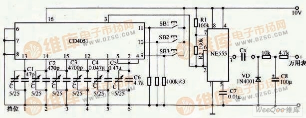
Multimeter measuring capacitance additional circuit diagram The circuit shown in the figure is an additional circuit diagram for measuring the capacitance of the multimeter. In this circuit, NE555 and R1, R2 and Cl~C6 form a pulse oscillator, and its output pulse frequency is different with C1~C6 respectively. Its frequency is 100kHz, 10kHz, 1kHz, 100Hz, 10Hz and 1Hz. 6 blocks. The corresponding capacitance measurement range is: 100pF, 1000pF, 0.01μ, 0.1μF, 1μF and 10μF. The multimeter measuring capacitance additional circuit uses a single 8-way analog switch CD4051 as a shift switch. Since it is controlled by the on and off of the transistors in the circuit, the mechanical switch does not have poor contact. The CD4051 is a binary-controlled electronic switch that combines the different combinations of pushbutton switches SB1~SB3 to form a 6-speed measurement conversion. Stainless Steel Decorative Tube Stainless Steel Decorative Tube,Stainless Steel Decorative Tube For The Kitchen,High Precision Stainless Steel Decorative Tube ShenZhen Haofa Metal Precision Parts Technology Co., Ltd. , http://www.haofametals.com