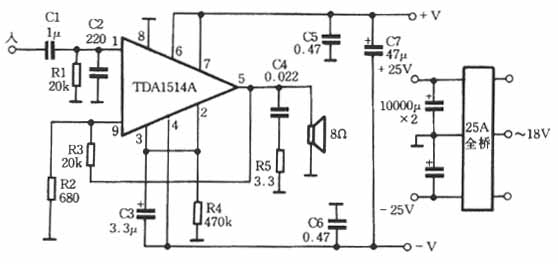
Simple power amplifier made with TDA1514 TDA1514A is a familiar high-quality power amplifier IC. If you follow the improved circuit shown in Figure 5-55, you can make a high-fidelity power amplifier. Due to the use of imitation integrated assembly process, making the production is particularly easy, but also makes the excellent performance of TDA1514A can be fully utilized. The production process is now introduced as follows. ã€Component welding press】 [Installation of circuit board and heat sink] ã€Complete machine assembly】 (3) If the cabinet is a metal shell, add an insulating plate between the transformer and the bottom plate and fix it. line. The specific method is: take a 3mm thick metal plate, the size is 50mmX200mm. At one end, fix a thick copper wire with a copper screw to make a ground wire. Choose a dark and humid place inside or outside the house, smash this aluminum plate underground, the deeper the better, and keep the ground wet here. It is necessary to connect to "earth" (referring to the earth), which can eliminate the annoying power supply interference noise, and your clean and clear sound quality, and can also eliminate the danger caused by static electricity. As a final reminder, when you use several machines online, the "earth" connected to the earth can only be connected to the power amplifier, not every machine can be connected to the earth, otherwise a ground loop will be formed, which will cause noise. Adopt integrated manufacturing process, with high signal-to-noise ratio (aluminum plate acts as a shielding layer): easy to manufacture (no corrosion, only knife engraving), short production cycle (1 day for all the process), convenient disassembly and maintenance, Even the enthusiasts of Gangrenmen, as long as they are made according to the method introduced in this article, can also achieve the desired effect. Other single-row pin power amplifier ICs are also suitable for making amplifiers using this method, such as TDAI521, LA440, etc. Follow WeChat Download Audiophile APP Follow the audiophile class related suggestion 
Carve the circuit board with a broken saw blade as shown in Figure 5-56. For the sake of beauty, polish the copper foil surface of the printed circuit board with No. 0 sandpaper, and burnish the components on the copper foil surface as shown in Figure 5-56. The component pins should be as short as possible. In order to increase the welding reliability, the component pins can be bent for a short period of flat welding. A layer of tin should be lined on the copper of the positive and negative poles of the power supply and the signal output end to enhance conductivity. The input capacitor should use the element polar capacitor. After the components are soldered, the IC is soldered, the pins do not need to be processed, and they are soldered flat on the copper skin.
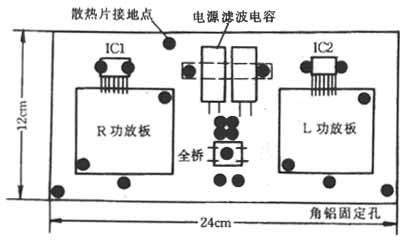
Choose a 5mm thick flat aluminum plate (copper plate is better), the size is not less than 12cmX24cm. Drill holes on the aluminum plate as shown in Figure 5-57, with an aperture of 4mm, used to install circuit boards, power filter capacitors, etc. The opening is determined according to the position of the fixed hole of the printed board and the specific production situation. The figure is the reference schematic position of the left and right channel circuit boards, filter capacitors, full bridge, etc. installed on the aluminum plate. The circuit board and related components should pay attention to the insulation problem with the heat sink. The positive and negative power leads from the filter capacitor to the circuit board are single-stranded wires, which are convenient for bending and shaping. Some wires need to be led out from behind through the aluminum plate. The full bridge adopts a square type with a central fixing hole. The filter capacity should be at least 10000uF / 35V, and a thin layer of mica sheet insulation should be added between the power amplifier IC and the aluminum plate. The mica sheet is coated with thermal grease on both sides, as shown in Figure 5-58. Finally, ground the entire aluminum plate. 
The assembly of the whole machine is very simple, just assemble as shown in Figure 5-59. It is worth noting the following:
(1) The power amplifier output uses a large terminal, and the ground wire is connected to the ground terminal of the filter capacitor, not the ground terminal of the circuit board.
(2) The dedicated signal cable is used for the internal signal cable. It is better not to use the very thin shielded cable on the market, but also use a slightly thinner 75ohm coaxial cable.
(4) The negative pole of the lotus socket for signal input should be insulated from the housing, and the housing of the potentiometer should be grounded.
ã€Installation of Earth Ground】
Households living in buildings using three-core sockets with grounding terminals are more convenient and effective. The ground wire in the socket should be connected to the ground end of the cabinet. For users who do not have a ground wire, they can barely connect a thick wire from the water pipe to make a ground wire (this method is not good for grounding and is not safe), or self-made simple ground 


'+ data.username +'
[Photo] Simple power amplifier made with TDA1514
Interesting and informative information and technical dry goods
Create your own personal electronic circle
Lock the latest course activities and technical live broadcast
comment
Publish