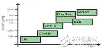
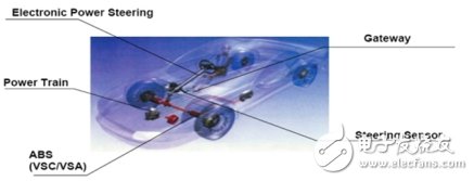
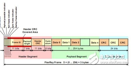
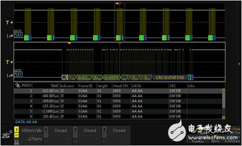
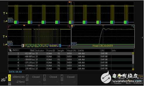
The FlexRay communication protocol is a high-speed automotive bus system with fault tolerance. It has been maturely used in the electronically controlled damping and main control suspension systems of the BMW X5. Here we will drink everyone to understand the FlexRay protocol and the corresponding decoding scheme. FlexRay is a high-speed deterministic, fault-tolerant automotive bus system. In most cars today, data exchange is mainly carried out via the CAN bus. The emergence of new x-by-wire system design ideas has also led to an increasing demand for information transmission speed, especially fault tolerance and time certainty. FlexRay meets these new requirements by passing information in defined time slots, as well as fault tolerance and redundant information transfer on both channels. The FlexRay topology can be divided into single channel and dual channel, including single channel bus type, single channel star type, single channel hybrid type and dual channel independently selectable topology. Figure 1 shows a single-channel bus type, and Figure 2 shows a two-channel topology. Figure 1 Single channel bus topology Figure 2 Dual Channel Bus Topology · FlexRay physically communicates over two separate buses, with a total data rate of up to 20 Mbit/s; · FlexRay has reliability features, especially its redundant communication capability, which enables complete network configuration replication and progress monitoring through hardware; FlexRay supports a variety of topologies such as bus, star, and hybrid topologies. Figure 3 Comparison of data rates for each protocol Although FlexRay itself does not ensure system security, it can support the design of a safety-oriented system such as the X-by-Wire system. Figure 4 FlexRay application system A data frame consists of a frame header, a valid data segment, and a frame tail. As shown in Figure 5: Figure 5 FlexRay data frame · Frame header 1. Reserved bits (1 bit) to prepare for future expansion; 2. The preamble indication (1 bit) of the load segment indicates the vector information of the load segment of the frame; 3. Empty frame indication (1 bit), indicating whether the data frame of the load segment is zero; 4. Synchronization frame indication (1 bit) indicating that this is a synchronization frame; 5. The start frame indication (1 bit) indicates whether the node transmitting the frame is a start frame; 6. Frame ID (11 bits) indicating the ID assigned to each node during system design; 7. Valid data length (7 digits) indicating the length of valid data; 8. Head CRC (11 bits) indicating the CRC calculation value of the sync frame indicator and the start frame indicator; 9. Cycle (6 digits). Indicates the period count of the node that transmitted the frame during the frame transfer time. · Effective data section 1. The data part is represented by data0, data1... in the figure; 2, information ID; 3. Network management vector. · End of frame There is only a single data field, the CRC part, including the frame header CRC and the CRC of the data frame. Relying on the powerful computing platform of the ZDS4054 Plus oscilloscope, the decoding function of the FlexRay protocol is available as standard. It can decode 512M full-memory FlexRay data and monitor vehicle communication signals. The information of each frame can be viewed in the event table, as shown in Figure 6 below: Figure 6 Flexray bus decoding Perform anomaly analysis on long-term monitoring data, and use the dual ZOOM multi-window display function in the zoom mode of the oscilloscope to perform multi-window abnormality monitoring and analysis on the signal, and analyze one data frame or one. The rise time of the rising edge is analyzed and measured, and the data changes in the event table can be observed in real time, as shown in Figure 7 below. Figure 7 Flexray detail analysis Transparent Led Film Screen,Adhesive Transparent Led Display,Adhesive Led Transparent Film Screen,Transparent Led Display Film Screen Guangdong Rayee Optoelectronic Technology Co.,Ltd. , https://www.rayeeled.com

