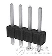
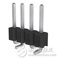
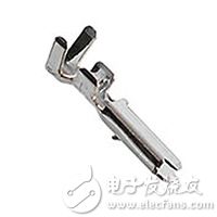
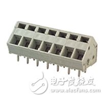
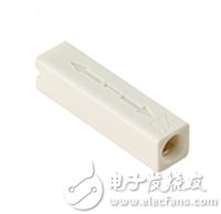
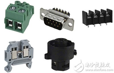
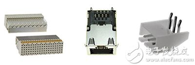
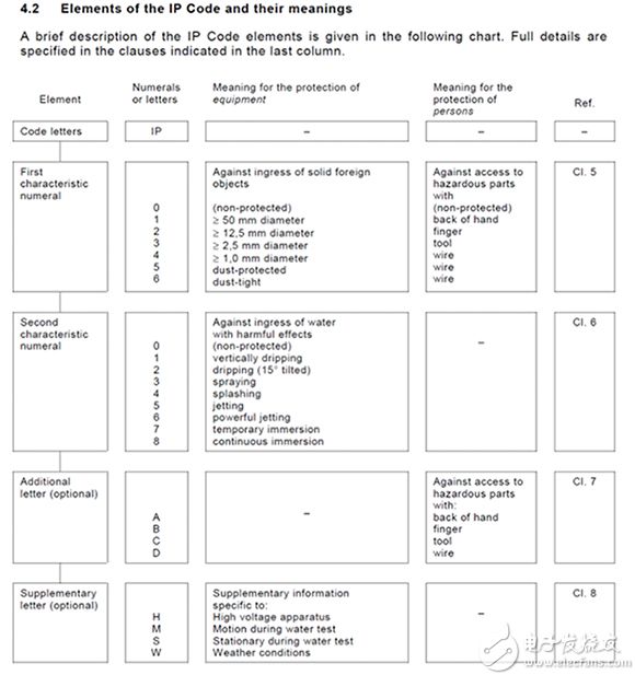
Connectors are a common part in almost any electronic project. Understanding the available connectors and the specifications and precautions to remember is very important in the design process. You don’t want to find that you need to add content and adjust the project to accommodate this change when the project is nearing the end, which will lead to increased time and expense costs. If you choose a connector for your project, you need to consider some considerations when specifying connector requirements. Some common problems include: How many contacts does the connector need? How do you want or need each connector to install? What is the installation method and what is required for installation? What termination method do you need or want for your application? Does the connector used need intrusion protection? How much voltage and current do you expect the connection to withstand? In many cases, the number of contacts required by the connector is known. However, sometimes the other needs of the overall application and the availability of each connector will ultimately affect the specifications of the selected connector. In addition, you need to further consider the power supply that the connector needs to handle, because this will affect the selected connector. As the power capacity of connectors continues to increase, you will find that the total number of contacts for any package/case size will drop. This is because larger wire gauges and/or higher voltages require more space. Some manufacturers have tried to increase the voltage rating by adding more isolation between the contacts and increasing the total "distance" of the arc from one contact to the other. In addition, some connectors have ground contacts built into the remaining contacts. These contacts are longer than the other contacts in the connector and are used to reduce/eliminate arcs between two mating/non-engaging connectors. In addition, the following points should be kept in mind and considered during the selection of the connector: How many connectors and contacts do you need or willing to use for power input/output enclosures? General contact combination type of connector Power contact only Signal contact only Power and signal contacts Signal + ground contact For projects where only one connector can be used, it may be necessary to use a slightly larger connector to accommodate all contacts. If the signal and power contacts are separated, the required installation space will increase. However, this may be a general layout requirement of the application, or the function of the application may cause the two contacts to be separated. The project also needs to consider how you want to install each connector. The following are examples of several installation types and provide sample links. PCB pin through holes-where the terminal pins of the connector are used to mount/fix the connector to the circuit board through the holes on the circuit board. Circular connector D-Sub connector Rectangular connector-pin seat, male pin Rectangular connector-pin socket, female socket PCB surface mount-where the terminal pins of the connector are used to mount/fix the connector to the circuit board, and the pins are placed on the contact pads on the surface of the circuit board. Circular connector D-Sub connector Rectangular connector-pin seat, male pin Rectangular connector-pin socket, female socket Panel installation-where there are reserved holes on the surface or panel, and the connector passes through the hole or is placed against the hole. Since the connector is installed on the circuit board behind the panel, the fixing method can be screw and nut or directly fixed in place. Rectangular connector-free hanging, panel mount Circular connector Circular connector-shell Free hanging/cable mounting-the connector is mounted/mounted to the cable at its termination. Circular connector Circular connector-shell Rectangular connector-shell Circuit board/card edge/prepared hole mounting-For card edges, the termination is close to the edge of the circuit board. In many cases, the connector will be modified for use at the edge. For the reserved holes on the board, the situation is similar because they are close to the edge of the circuit board. However, a part of the circuit board has holes reserved so that the connector has a flat profile. These two types of installation methods are to achieve a flatter overall appearance of the circuit board. In addition, these two types of connections can also be used when there is a lack of available space on the circuit board or due to other design requirements. USB, DVI, HDMI connectors Coaxial connector (RF) Through-board mounting-similar to reserved hole mounting, but the difference is that this type of connector is not commonly found near the edge of the circuit board. Since they are installed through reserved holes on the circuit board, they are also similar to panel mount connectors. Some are terminated with through holes in the circuit board and soldered on the same side of the connector engagement, while others are surface mounted to the side of the circuit board where they are mounted (the side opposite the connector engagement side). Examples of this type of connector are as follows: Terminal-Wire to Board Connector Solid state lighting connector Rectangular connector-onboard, direct wire to board The terms "installation" and "termination" are often used interchangeably, but it should be remembered that they are not always interchangeable, and there is a difference between the two. Installation refers to how the entire project and the connector are connected/fixed/attached as a whole. Termination refers to how to make electrical connections. Through-hole mounting and surface mounting in most cases refer to connectors that can be mounted and terminated in a specific way (see "Termination Methods" below for details). The following are possible examples of mounting, engagement, and termination combinations: Connector 1 Panel installation Use right-angle surface mount contacts to terminate to the circuit board The connector 2 of the mating connector 1 is Free hanging connector Threaded termination What termination method is required for each end or each connection? If there are no specific types of requirements specified in advance, the termination method can be determined by personal preference. However, some applications may require a specific type of termination. Solder Termination-For connectors, this termination method is suitable for many applications. However, if it is an application in a high temperature area, more mechanical termination methods may need to be considered. Soldering can be used for wire termination and circuit board termination connections. Therefore, this type of termination includes a variety of connector welding methods. Through-hole soldering and surface mounting as described above, describe a type of mounting and termination. Figure 1: Solder termination of a typical connector. Through-hole soldering-pins are left on the terminal side of the connector to pass through the pre-perforated holes on the circuit board, and copper pads are usually laid on the opposite side of the circuit board on the access side of the through-hole connector. After placing it in place, it will be welded and fixed. Figure 2: This board-to-board/board-to-cable connector is connected to the PCB by through-hole soldering. Surface mount termination-the connector pins and mounting pads are located on the same side of the PCB. The connector can be manually placed and soldered in place, or soldered in place by reflow soldering and wave soldering. Note that some circuit board/card edge connectors are also surface mount types. Figure 3: This board-to-board/board-to-cable connector uses surface mount soldering to the PCB. Crimping-This type of termination is very robust and reliable and can be used to terminate wires. However, this depends on the quality of the crimp and the correct installation in the contact housing. In order to achieve high-quality crimping and overall connection, it is necessary to ensure that the correct contacts and the correct crimping tools are used for the housing. For these contacts, tool selection is an important step. If the final quality is not a key consideration, other tools or lower-cost devices can be used. However, if you want to consider the final quality, you need to use the tools recommended by the manufacturer, the relevant wire preparation steps, and any crimp quality data provided by the manufacturer for post-crimp inspection (note: not all inspections are required, as long as sample verification is required. can). If the tools and correct steps are not used, and the connection is wrong, most manufacturers of this type of connector will not provide support or warranty. Figure 4: Example of contacts crimped to stripped wire conductors. Press-in/plug-in- This type can be either a permanent termination or a releasable termination, and it also has fairly good reliability and robustness. However, if it is used in a high-vibration environment, it is recommended to check the anti-vibration strength of the connector. This type of termination usually only needs to peel the wire and press it into the connector, or activate the locking lever to the unlocked state, insert the wire, and move the locking lever to the locked state. For the type that can loosen the wire, some mechanism can be built into the connector, or a tool such as a flat-blade screwdriver needs to be pressed into the groove of the housing. Figure 5: This board mount connector terminates with stripped wires, which are pressed into the lower opening. In this case, use a tool to loosen the wire when needed. Figure 6: This free hanging connector can terminate stripped wires by pressing/inserting the wires into one end. For this particular type of connector, the wire can be loosened by twisting and pulling. Screw terminals-this type of termination is used in various connector types and can be used in different ways. The following are examples of different types of threaded terminal terminals: 281-2879-ND|609-4193-ND|732-2759-ND|281-3218-ND|609-3832-ND|WM7477-ND|732-10091-ND|ED2947-ND|1776293-3-ND| WM5751-ND|WM5761-ND Figure 7: These are examples of connectors that use threads to terminate wires. Wrap around Examples include CWN-370-50-0000. This type of connector can be used for wire-wrapping applications. CWN-370-50-0000 is designed to be installed on the PCB first, and then wire it up after being soldered in place. These connectors are not necessarily used in products that will be mass-produced. They are used for high-frequency end products and low-volume product prototypes. The following link shows information about routing practices. Figure 8: These are examples of connectors that use wire wrap methods to terminate wires. Press-fit-can be a solderless termination type. Therefore, this method can help reduce the overall cost of the project. Note that press-fit terminations are usually designed not to be used at the same time as welding. However, if you need to solder this type of connector for some reason, you must be aware that doing so will affect the parts, and the manufacturer may not provide any support for the problem. It is recommended that these connectors be carefully considered and tested before soldering. In addition, this type of termination will be equipped with available tools to ensure that the connector is inserted smoothly and fully placed in place. It is recommended to use the tools specified by the manufacturer. If the manufacturer does not specify a tool, you may need to contact the manufacturer directly, and they may need to discuss application requirements with you. Digi-Key's introduction to pressing technology is an excellent reference for this type of technology. Figure 9: These are examples of connectors that can be terminated to reserved holes on the mounted circuit board, including through-hole and press-fit types. If it is a relatively ordinary application environment, and no extreme value is expected to occur, then almost any connector is suitable for the specified specific needs. But when designing projects for harsh application environments-such as the connectors used may encounter vibration, motion shock, shielding, environmental intrusion, oil, solvent, or any kind of chemicals and corrosion-you need to keep these characteristics in mind during the selection process. Vibration and dynamic shock For connections inside the housing, you can choose connectors with additional features such as mounting bosses and other larger pads/pins. Omron's XH5 product brief offers some options that just include these two features. Starting from page 3, the document provides connector diagrams and the installation modes available for each connector to make full use of the installation features. For connections that need to go in and out of the enclosure, there are quite a few options for any particular type of connector. The connector specifications currently under consideration should be consulted to see if they have been tested and are suitable for the expected shock and vibration levels that the project may encounter. shield When environmental magnetic noise is a key consideration or causes problems on a regular basis, the connector should have a shielding function. For connectors that use shielding, it may be necessary to consider whether only certain parts need to be shielded, or (in the case of cables) whether the entire path needs to be shielded uniformly. Take the Ethernet cable as an example. If the environmental conditions are good, you can use some basic Ethernet cables and 8-bit modular connectors. However, as the environmental magnetic noise increases, it is necessary to consider/use modular connectors and Ethernet cables with shielding functions. WurthElectronik’s application note for effective EMI shielding concepts is a good reference for information about shielding issues. For oils, solvents, or any type of chemicals and corrosion, it may not be possible to find options that meet other specifications and have ratings that are suitable for such environments. In some cases, if the ratings do not meet the requirements, it may be necessary to communicate with the manufacturer to obtain connector variants that can be used in such environments. Here is some information about such environmental hazards: Connector Selection Guide for Harsh Environments, Amphenol Electrochemical (electrolytic) corrosion, Samtec Does the connector need intrusion protection The intrusion protection level indicates the degree to which the connector can prevent solids/dust and moisture/water from entering its protected area. If this is an important consideration, it should be considered in the selection of the connector so that all other options that do not meet the intrusion protection requirements can be excluded. Intrusion protection grade format IPX 1 X 2 YZ IP=Intrusion protection X 1 0-No special protection 1-Provide protection against solids above 50mm, such as accidental contact with human hands 2-Provide protection against solids above 12mm, such as fingers 3-Provide protection against solids above 2.5mm (tools and wires) 4-Provide protection against solids above 1mm (tools, wires and thin wires) 5-Provides limited intrusion protection against dust (no harmful deposits) 6-Completely dustproof X 2 0-No protection 1- Protection against vertically falling water droplets, such as condensate 2- Protection against direct spray water that deviates from the vertical direction by up to 15° 3- Protection against direct spray water that deviates from the vertical direction up to 60° 4- Spray water protection for all directions-limited intrusion allowed 5- Low-pressure water jet protection for all directions-limited intrusion 6- Temporary flood protection, such as used on ship decks-limited intrusion allowed 7- Protection against immersion from 15cm to 1m 8-Long-term pressure immersion protection Y and Z uncommonly used Can be used to indicate a variety of specifications. The following information helps define Y and Z This is the information I obtained from the engineering design team of Switchcraft-"IP code is defined in IEC60529. The snapshot provided below contains basic information." (Figure 10) Figure 10: IP codes defined in IEC60529. (Image source: Switchcraft) Other specifications can be expanded on optional numbers. DIN40050 adds the "K" option to the electrical equipment of road vehicles. For example, IP69K means a dust-proof (6) enclosure for high pressure/steam jet cleaning (9K) protection. For detailed specifications, please refer to the following link: Omron's intrusion protection (IP) level Wikipedia's IP code EngineeringToolbox's IP-intrusion protection level How much rated current is required? When choosing a connector, you should choose a connector that can handle the maximum expected current. It is recommended to choose a connector that can handle higher than expected current as much as possible to provide margin for any unexpected overcurrent. Some connectors do not list the current in the documentation. In this case: If it is a board mount connector, try to find the mating point for the cable installation. The wire gauge of the connector can be used to find the rated current. Please refer to this link to view AWG rated current conversion. WiFi 5 Outdoor Wireless AP is a wireless access point for outdoor environments. It is a device based on the IEEE 802.11ac standard, also known as WiFi 5. The device has a number of features and advantages that make it ideal for wireless networking in outdoor environments. WiFi 5 Outdoor Wireless AP,WiFi 5 Outdoor Wireless AP oem,the best WiFi 5 Outdoor Wireless AP Shenzhen MovingComm Technology Co., Ltd. , https://www.movingcommiot.com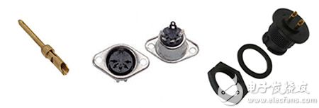

First, the WiFi 5 Outdoor Wireless AP has strong wireless signal coverage. It can provide longer transmission distances and wider coverage, enabling users to obtain a more stable and reliable wireless connection in outdoor environments. This is important for large outdoor Spaces such as campuses, parks, stadiums and city squares.
Second, WiFi 5 Outdoor Wireless AP has high wireless transmission speed. It supports multiple radio bands and multiple MIMO (multiple input multiple output) antenna technologies, which can provide higher data transfer rates. This means that users can enjoy wireless networking experiences such as faster web browsing, file downloads and video streaming in an outdoor environment.
In addition, the WiFi 5 Outdoor Wireless AP offers excellent network capacity and performance. It supports more simultaneous connected devices and can meet the needs of a large number of users to access the wireless network at the same time. This is important for busy outdoor venues such as music festivals, exhibitions and sporting events. In addition, it also supports QoS (Quality of Service) functions, which can prioritize applications and devices that require high network performance, providing a better user experience.
WiFi 5 Outdoor Wireless AP also has strong anti-interference capability. It uses advanced wireless technology and channel selection algorithms to automatically detect and avoid interference with other wireless devices. This makes it perform well in high-density wireless environments, such as city centers or business districts.
In addition, WiFi 5 Outdoor Wireless AP has good security. It supports security protocols such as WPA2-PSK (Wi-Fi Protected Access 2 Pre-Shared Key) and WPA3 (Wi-Fi Protected Access 3), which protect wireless networks from unauthorized access and data breaches. In addition, it supports features such as virtual private networks (VPNS) and firewalls to further enhance the security of the network.
The WiFi 5 Outdoor Wireless AP also has the advantage of being easy to install and manage. It usually has a user-friendly Web interface that makes it easy to set up and configure wireless networks. In addition, it supports a centralized management system that can manage and monitor multiple wireless access points from a central console, greatly simplifying network management.
Finally, WiFi 5 Outdoor Wireless aps typically have a durable design and protection against harsh outdoor environments. It is usually waterproof, dust-proof and earthquake-resistant, and can operate stably in various weather conditions. This makes it ideal for long-term use in outdoor places.
In summary, the WiFi 5 Outdoor Wireless AP is a device that provides stable, high-speed and secure wireless connectivity in outdoor environments. It has the characteristics and advantages of strong wireless signal coverage, high-speed wireless transmission speed, excellent network capacity and performance, strong anti-interference ability, good security, easy installation and management, and durable design and protection performance. This makes it ideal for deploying wireless networks in outdoor locations.