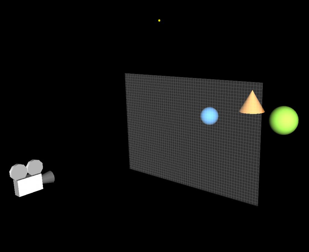
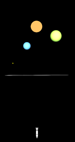
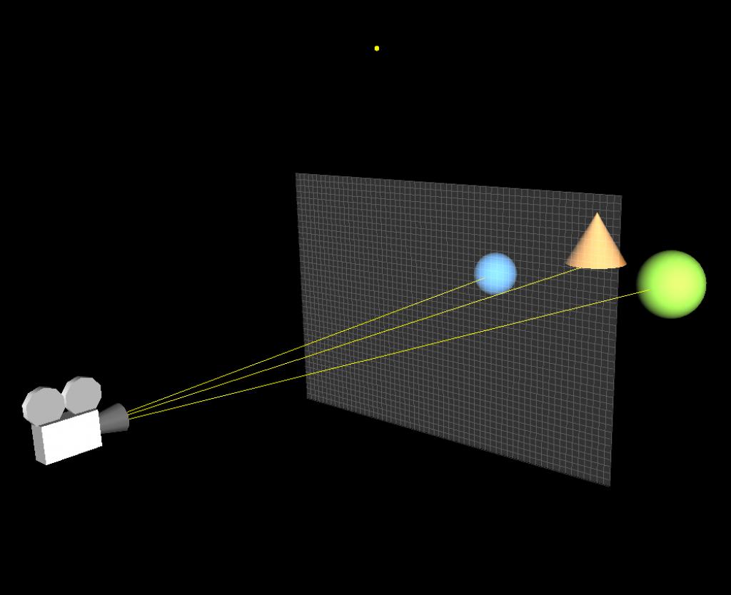
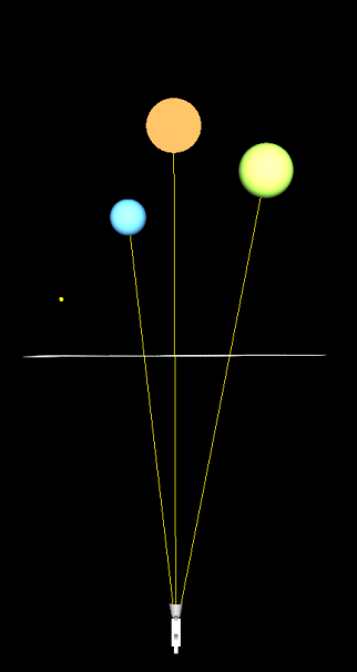
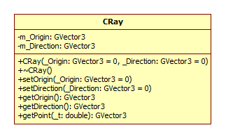
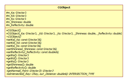
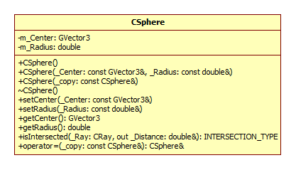
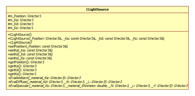
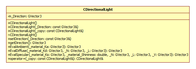
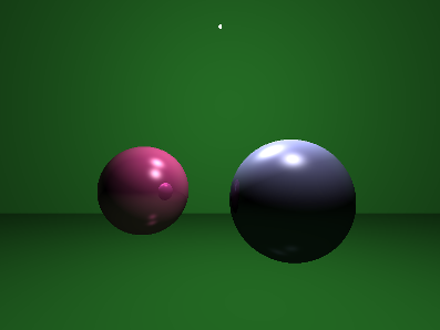
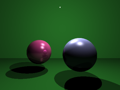
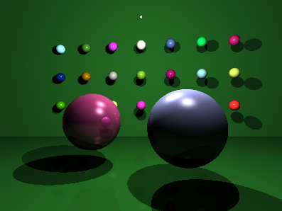
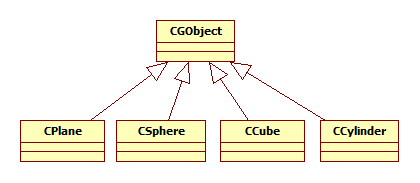
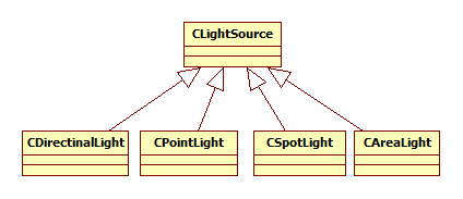
Introduction This article refers to the address: http:// This article will introduce ray tracing techniques. In the field of computer graphics, this technique is commonly used to generate high quality photo-level images. When calculating lighting for a scene, the phong lighting model can be calculated by fixing the graphics rendering pipeline. Due to the characteristics of the model, the rendered object looks like a plastic texture. If you want to render an object that has a metallic feel and reflects the surrounding environment, the phong model can't do anything about it. Compared to fixed rendering pipelines, programmable graphics rendering pipelines are much more powerful, although many realistic lighting effects can be achieved, such as the use of environmental maps to reflect the effects of objects on the environment. But this kind of environmental reflection can only reflect the image that has been saved in the Cube Map. In the real world, if there are many other objects around an object that reflects the surrounding environment, they will reflect each other. The general environment mapping technology does not achieve this effect, so the ray tracing technique is used when rendering photo-level images. The text will also use the C++ object-oriented approach to ray tracing. principle Before introducing the principle, consider a question: How do we see objects in the real world? We can see objects because there are reflected rays on our objects that reach our eyes. No light comes into the eyes, we can't see anything. We also often see that the surface of one object can reflect another object. This is also because after the reflected light from the surface of the reflected object reaches the surface of the object, the object continues to reflect the light into our eyes, so we see the effect of the surface of the object reflecting other objects. Now, we will reverse the direction of the light that reaches the eye from the surface of the object. Let's take a look at Fig1 below. In Fig1, it is a virtual scene. There are 2 balls and 1 cone in the scene. The white dots represent the light source. The middle quadrilateral is the virtual screen. The small squares on the screen represent the small squares. Pixel, the position of the camera represents the position of the observer's eyes. (a) (b) Fig1 ray tracing scene The principle of ray tracing is to emit a strip of light passing through each pixel from the position of the camera. If the ray intersects with an object in the scene, then the color of the intersection can be calculated. This color is the color of the corresponding pixel. Of course, when calculating the pixel color, first calculate all the quantities related to the illumination calculation at the intersection, such as normal, incident and reflected light. (a) (b) Fig2 Light and space objects intersect As you can see in Fig2, the rays from the camera pass through each pixel in turn, and three of them are shown. These rays all have intersections with objects, and the intersection points of different objects are calculated differently. The calculation method of the intersection of the ray and the plane and the calculation method of the intersection of the ray and the sphere are completely different. For the convenience of calculation, here is just a ball. If an object can reflect the surrounding environment, then when a ray intersects the object, the ray will also reflect and refract at that point. For example, in Fig2, when the ray and the blue sphere intersect, the light will reflect, and the reflected light may intersect the orange cone and the green sphere, so we can see the orange cone and the green sphere on the surface of the blue sphere. The principle of the entire ray tracing is as simple as this, but there are a lot of things to pay attention to in practice. practice It's easier to implement ray tracing with an object-oriented approach than with a structure-oriented approach. Because in the whole process of ray tracing, it is easier to abstract the common features of objects, such as we can abstract rays, objects, light sources, materials and so on. Of course, the most basic class is the vector class, which is important when calculating lighting. Here we assume that we have implemented a three-dimensional vector class, GVector3, which provides all the operations related to the vector. In addition to vectors, we can first think of a class about ray, called CRay. The most basic for a ray is its starting point and direction, so in the CRay class diagram, you can see two private member variables m_Origin and m_Direction, which are all of the GVector3 type. Since the design principles of the class should satisfy the encapsulation of the data, since the starting point and direction of the ray are private, then a public member method is required to access them, so we also need the set and get methods. Finally, the getPoint(double) method gets the point on the ray by passing the parameter t to the parametric equation of the ray. After implementing the ray CRay class, then when using ray tracing to calculate the color of each pixel, create an instance of CRay for each pixel. For(int y=0; y<=ImageHeight; y++) { For(int x=0; x<=ImageWidth; x++) { Double pixel_x = -20.0 +40.0/ImageWidth*x; Double pixel_y = -15.0 +30.0/ImageHeight*y; GVector3 direction = GVector3(pixel_x, pixel_y,0)-CameraPosition; CRay ray(CameraPosition, direction); // call RayTracer function } } As you can see from the code above, two for loops are used to scan each pixel and then calculate the position of each pixel in the loop. If we assume that the quadrilateral screen is in the xy plane in Fig1, the length and width are 40 and 30, respectively, and the coordinates of the upper left vertex and the coordinates of the lower right vertex are (-20, 15, 0) and (20, -15, 0), respectively. In order to map the screen to a window with an actual resolution of 800*600, the coordinates pixel_x and pixel_y of each pixel on the virtual screen are required. Then, for each pixel, a ray is passed through it, and the direction of the ray is naturally the direction of the difference between the position of the pixel and the position of the camera. It should be noted that the resolution ratio of the actual window should be the same as the ratio of the length and width of the virtual screen, so that the rendered image looks correct in length and width. Now let's consider the objects in the scene. An object may have many features that describe it, such as shape, size, color, material, and so on. Using an object-oriented approach, you need to abstract the common features of these objects. Below is an abstracted object class GCObject. There are five member variables of CGObject class, which represent the ambient light reflection coefficient (m_Ka), diffuse reflection coefficient (m_Kd), specular reflection coefficient (m_Ks), specular reflection intensity (m_Shininess) and environmental reflection intensity (m_Reflectivity). The first four variables are the most basic quantities needed to calculate the illumination, and the ambient reflection intensity indicates the ability of the object to reflect the environment. The types of these member variables are protected, because we want to put CGObject as the base class of the object, these protected member variables can be inherited by the subclass of the class. All get methods and set methods of this class can be inherited by subclasses, and all methods that inherit subclasses of this class have the same method. This class also has two virtual member functions, getNormal() and isIntersected(). The function of the getNormal() function is to get the normal of a point on the surface of the object. It takes a parameter _Point of type GVector3 and returns the normal at the point _Point of the object surface. Of course, the method of obtaining the normal on the surface of different objects is different. For example, for a plane, the normals of all points on the plane are the same. For the ball, the normal of each of the spheres is the difference vector between the intersection p of the sphere and the c of the sphere. NSphere = p - c So set getNormal() to a virtual member function to implement polymorphism in the class. Any subclass that inherits the method can implement its own getNormal() method. By the same token, the function isInserted is also a virtual member function, which accepts the parameter ray CRay. Distance and Distance, CRay is an input parameter used to determine the intersection of the ray and the object. Distance is the output parameter. If the object intersects the ray, the distance from the camera to the intersection is returned. Distance should also have a large initial value, indicating that the object intersects the ray at infinity, which is used to determine that the object and the ray have no intersection. The function isIntersected() also returns an enumeration type INTERSECTION_TYPE, defined as follows: Enum INTERSECTION_TYPE {INTERSECTED_IN = -1, MISS = 0, INTERSECTED = 1}; INTERSECTED_IN indicates that the ray starts from the inside of the object and intersects with the object. The MISS ray and the object have no intersection. INTERSECTED indicates that the ray starts from the outside of the object and intersects with the object. The calculation method of the intersection of ray and different objects is different, so the function is a virtual function, and the subclass that inherits the function can implement its own isIntersected() method. The following code can determine if a ray has an intersection with all objects in the scene and returns to the closest one to the camera. Double distance = 1000000; // initialize infinite distance GVector3 Intersection; // intersection For(int i = 0; i { CGObject *obj = objects_list[i]; If( obj->isIntersected(ray, distance) != MISS) // Determine if there is an intersection { Intersection = ray.getPoint(distance); //If intersected, find the intersection to save to Intersection } } For the convenience of calculation, here is a ball, for example, to create a CSphere class that inherits from CGObject. As a ball, you only need to provide the center of the ball and the radius Radius to determine its geometric properties. So the CSphere class has only two private member variables. In all member functions, we focus on the isIntersected() method. INTERSECTION_TYPE CSphere::isIntersected(CRay _ray, double& _dist) { GVector3 v = _ray.getOrigin() - m_Center; Double b = -(v * _ray.getDirection()); Double det = (b * b) - v*v + m_Radius; INTERSECTION_TYPE retval = MISS; If (det > 0){ Det = sqrt(det); Double t1 = b - det; Double t2 = b + det; If (t2 > 0){ If (t1 < 0) { If (t2 < _dist) { _dist = t2; Retval = INTERSECTED_IN; } } Else{ If (t1 < _dist){ _dist = t1; Retval = INTERSECTED; } } } } Return retval; } If the ray and the ball have intersections, then the intersection is definitely on the sphere. The point P on the sphere satisfies the following relationship. | P – C | = R It is obvious that the difference between the point of the sphere and the center of the sphere is equal to the radius of the sphere. Then the parametric equation of the ray is brought into the above formula, and then the root solution formula is used to judge the solution. The specific method is not detailed here. Interested students can refer to another article "Using OpenGL to implement RayPicking". This article explains in detail the calculation process of ray and ball intersection. Now we have implemented ray CRay, sphere CSphere, and an important role - the light source. The light source is also a kind of object that can be inherited from our base class CGObject class. To make a difference here, we create a base class CLightSource for all the lights, and then derive different light source types from it, such as parallel light DirectionalLight, point light CPointLight and poly light source CSpotLight. In this article, only the situation of parallel light sources will be explained in detail. Students who are interested in the other two light sources can implement them themselves. There are four member variables of the class CLightSource, which indicate the position of the light source, the ambient light component of the light source, the diffuse reflection component and the specular reflection component. Similarly, all set and get methods provide the same functionality for subclasses of this class. Finally, there are three virtual member functions, EvalAmbient(), EvalDiffuse(), and EvalSpecular(), whose names indicate their functions, respectively, and both return the value of the GVector3 type—the color. Since the calculation methods may be different for different kinds of light sources, they are set to virtual functions in preparation for future expansion. Here I put the lighting calculation in the light source class. Of course, you can also put it in the object class CGObject, or you can write a separate method to pass the light source and the object as parameters, and return the most return value after calculating the color. Which one is better to use depends on the specific situation. The above parallel light source class CDirectionalLight is a subclass of CLightSource, which inherits the three virtual function methods of the parent class. Let's take a look at the concrete implementation of these three functions. The calculation of ambient light is the simplest, multiplying the reflection coefficient of the material environment and the ambient light component of the light source. Ambient = Ia•Ka The code for calculating ambient light is as follows GVector3 CDirectionalLight::EvalAmbient(const GVector3& _material_Ka) { Return GVector3(m_Ka[0]*_material_Ka[0], m_Ka[1]*_material_Ka[1], m_Ka[2]*_material_Ka[2]); } The calculation of diffuse reflection is slightly more complicated than ambient light, and the calculation formula of diffuse reflection is Diffuse = Id•Kd• (N•L) Where Id is the diffuse reflection component of the light source, Kd is the diffuse reflection coefficient of the object, N is the normal, and L is the incident light vector. GVector3 CDirectionalLight::EvalDiffuse(const GVector3& _N, const GVector3& _L, constGVector3& _material_Kd) { GVector3 IdKd = GVector3( m_Kd[0]*_material_Kd[0], m_Kd[1]*_material_Kd[1], m_Kd[2]*_material_Kd[2]); Double NdotL = MAX(_N*_L, 0.0); Return IdKd*NdotL; } The calculation of specular reflection is more complicated than ambient light. The calculation formula of specular reflection is Specular = Is•Ks• (V·R)n among them R = 2(L•N) • NL Is is the specular reflection component of the source, Ks is the specular reflection coefficient of the object, V is the camera direction vector, R is the reflection vector, and n is the reflection intensity Shininess. In order to improve the calculation efficiency, the HalfVector H can also be used to calculate the specular reflection. Specular = Is•Ks• (N•H)n among them H=(L+V)/2 Calculating H is much faster than calculating the reflection vector R. GVector3 CDirectionalLight::EvalSpecluar(const GVector3& _N, const GVector3& _L, constGVector3& _V, Const GVector3& _material_Ks, const double& _shininess) { GVector3 IsKs = GVector3( m_Ks[0]*_material_Ks[0], m_Ks[1]*_material_Ks[1], m_Ks[2]*_material_Ks[2]); GVector3 H = (_L+_V).Normalize(); Double NdotL = MAX(_N*_L, 0.0); Double NdotH = pow(MAX(_N*H, 0.0), _shininess); If(NdotL<=0.0) NdotH = 0.0; Return IsKs*NdotH; } Calculate the ambient light at the intersection of the ray and the object, diffuse and specular, then the color c of the corresponding pixel of the ray is C = ambient + diffuse + specular So, we can add a method in the code called Tracer(), which is to traverse each object in the scene, determine the intersection of the ray and the object, and then calculate the color of the intersection. GVector3 Tracer (CRay R) { GVector3 color; For(/* traverses each object*/) { If (/* if there is an intersection */) { GVector3 p = R.getPoint(dist); GVector3 N = m_pObj[k]->getNormal(p); N.Normalize(); For(/* traverses each light source*/) { GVector3 ambient = m_pLight[m]->EvalAmbient(m_pObj[k]->getKa()); GVector3 L = m_pLight[m]->getPosition()-p; L.Normalize(); GVector3 diffuse = m_pLight[m]->EvalDiffuse(N, L, m_pObj[k]->getKd()); GVector3 V = m_CameraPosition - p; V.Normalize(); GVector3 specular = m_pLight[m]->EvalSpecluar(N, L, V, m_pObj[k]->getKs(), m_pObj[k]->getShininess()); Color = ambient + diffuse + specular; } } } } If you want to render an object that reflects the surrounding environment, you need to modify the above Tracer() method slightly. Because the reflection is a recursive process, once the ray is reflected by the object, the same Tracer() method will be executed once. Calculate whether the reflected light and other objects still have intersections. Then, in the Tracer() method, a parameter depth representing the recursive iteration depth is added, which indicates the number of times the ray is reflected after intersecting the object. If it is 1, it means that the ray does not reflect after intersecting with the object, and 2 indicates ray reflection once. And so on. Tracer(CRay R, int depth) { GVector3 color; // calculate C = ambient + diffuse + specular If(TotalTraceDepth == depth) Return color; Else { / / Calculate the reflected ray Reflect at the intersection of the ray and the object; GVector3 c = Tracer(Reflect, ++depth); Color += GVector3(color[0]*c[0],color[1]*c[1],color[2]*c[2]); Return color; } } Create a scene and then execute the code to see the effect below. Fig3 ray tracing rendered scene 1 If you set the Tracer's recursion depth to be greater than 2, you can see that the two balls reflect each other. Although this ray tracing can be performed normally, the picture always seems to lack something. If you look closely, you will find that although there is a light source in the picture, the object has no shadow, and the shadow can increase the authenticity of the scene. To calculate the shadow, we should start from the light source. If there is an intersection between the ray and the object from the light source, and the ray intersects with multiple objects, then all the intersections except the first intersection are in the shadow. It's easy to understand. So, we need to modify some of the code. GVector3 Tracer(CRay R, int depth) { GVector3 color; Double shade = 1.0 For(/* traverses each object*/) { For(/* traverses each light source*/) { GVector3 L = pObj[k]->getCenter() - Intersection; Double dist = norm(L); L *= (1.0f / dist); CRay r = CRay( Intersection,L ); For ( / * traverse every object * / ) { CGObject* pr = pObj[s]; If (pr->isIntersected(r, dist)!=MISS) { Shade = 0; Break; } } } } If(shade>0) { // calculate C = ambient + diffuse + specular // Recursively calculate reflection } Return color*shade; } After adding the shadow calculation, run the program again and you will see the following effect. Fig4 ray tracing rendered scene 2 Finally, we can also let the ground reflect the object, and then add a lot of small balls on the wall to make the picture more complicated, as shown below. Fig5 ray tracing rendered scene 3 to sum up This article implements ray tracing rendering scenarios by leveraging an object-oriented approach. Using object-oriented methods to achieve ray tracing to enhance the scalability of the program, when rendering complex scenes or complex geometric objects, or when there are many light sources and complex lighting calculations, only need to inherit from the base class, and then use more State to achieve different rendering methods for different objects. As you can see from the class diagram above, you can easily extend the program with an object-oriented approach. Moreover, due to this structure of ray tracing, no matter how many objects are added in the scene, no matter how complex the object, this structure always renders the correct picture well. However, for ray tracing, the more complex the scene, the longer the rendering time is required. Sometimes it takes even a few days to render a frame of text. So good algorithms and program structure are very important for ray tracing. You can improve rendering efficiency through scene management, using GPU or CUDA. Copper-Clad Aluminum Core Wire,Copper Clad Aluminum Metal Wire,Copper Clad Aluminum Pure Copper Wire ,Copper Clad Aluminum Bimetallic Wire changzhou yuzisenhan electronic co.,ltd , https://www.yzshelectronics.com