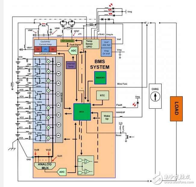
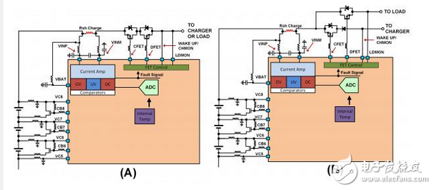
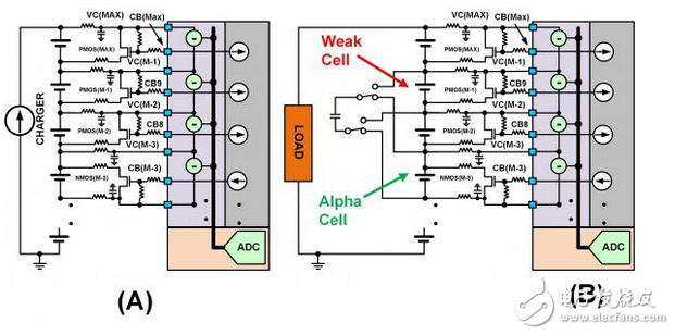
Today's electronic devices are more mobile and greener than ever, and advances in battery technology are driving this advancement and benefiting a wide range of products including portable power tools, plug-in hybrids, and wireless speakers. In recent years, battery efficiency (output power/size ratio) and weight have both improved significantly. Imagine how big and bulky the car battery is, and its main purpose is to start the car. With the latest advances in technology, you can switch to a lithium-ion battery to get your car started quickly. It weighs just a few pounds and is the size of a man. The constant changes in battery technology have prompted many newcomers to learn how to design battery management systems. This article provides a beginner's guide to the Battery Management System (BMS) architecture, discusses the main functional blocks, and explains the importance of each function block to the BMS system. Figure SEQ Figure * ARABIC 1: Simplified schematic diagram of the Battery Management System (BMS) function block. Battery management system architecture The Battery Management System (BMS) typically contains several functional blocks such as FET drive, current monitoring, cell voltage monitor, cell voltage equalization, real-time clock, temperature monitoring, and state machine. There are many types of BMS ICs on the market. From simple analog front ends (such as ISL94208 that provide equalization and monitoring functions and require a microcontroller) to stand-alone integrated solutions that operate autonomously (such as ISL94203), the grouping of function blocks varies widely. Now let's look at the use of each function block and the technology used, as well as the advantages and disadvantages of each technology. Turn off FET and FET drivers The FET driver function block is responsible for the connection of the battery pack and the isolation between the load and the charger. The behavior of the FET driver can be manipulated based on cell voltage measurements, current measurements, and real-time detection circuitry. Figures 2(a) and 2(b) depict two different FET connections between the load and the charger and battery pack. Figure SEQ Figure * ARABIC 2: Schematic diagram of a differently connected cut-off FET: (a) a single connection between the load and the charger, and (b) a two-terminal connection that allows simultaneous charging and discharging. Figure 2(a) requires a minimum number of battery pack connections, and the battery pack operating mode is limited to charging, discharging, or sleeping. The direction of the current and the behavior of the specific real-time detection determine the state of the device. For example, the ISL94203 has a CHMON that monitors the voltage on the right side of the cut-off FET. If the charger is connected and the battery pack is isolated, the current injected into the battery pack will cause the voltage to rise to the maximum supply voltage of the charger. At this point, the voltage level at the location of CHMON is tripped, allowing the BMS device to know that the charger is connected. The load connection is determined by injecting current into the load direction to determine if the load is present. If the voltage at the pin location does not rise significantly during current injection, the load is still present. The DFET of the FET driver then continues to turn off. The connection scheme of Figure 2(b) allows the battery pack to support discharge operation while charging. FET drivers can be designed to connect to the high or low side of the battery pack. The high side connection requires a charge pump driver to activate the NMOS FET. Use a high-end driver to have a solid ground reference for the rest of the circuit. Low-side FET driver connections are found in some integrated solutions to reduce cost because no charge pump is required at this time. Low-end connections also do not require high-voltage devices, which take up a larger chip area. Turning off the FET at the low end causes the ground point of the battery pack to be connected to float, making it susceptible to the noise of the injected measurement - which can affect the performance of some ICs. Fuel gauge / current measurement The fuel gauge function module is responsible for recording the charge flowing into and out of the battery pack. The charge is the product of current and time. There are many different techniques available for designing battery timing. One way to measure current is to use a current sense amplifier and an MCU with an embedded low resolution ADC. The current op amp operates in a high common-mode environment and is responsible for amplifying the differential signals on the shunt to support higher measurement resolutions. This design technique comes at the expense of dynamic range. Other technologies use high resolution ADCs or expensive fuel gauge ICs. Understanding the current consumption-time relationship of load behavior determines the best type of fuel gauge design. The most accurate and economical solution is to measure the voltage across the sense resistor using a 16-bit or higher resolution ADC with low drift and high common-mode rating. High resolution ADCs provide a large dynamic range at the expense of speed. If the battery is connected to an irregular load, such as an electric vehicle, the slow ADC may miss high amplitude and high frequency current spikes flowing to the load. For irregular loads, it may be more desirable to use a SAR ADC that may have a current op amp front end. Any offset error affects the total error (measured by the amount of battery charge). Over time, measurement errors can cause severe charge state battery pack errors. When measuring charge, a measurement offset of 50uV or less is sufficient at 16-bit resolution. Single cell voltage and maximize battery life Monitoring the voltage of each cell in the battery pack is essential to determining the overall health of the battery pack. All single cells have an operating voltage window during which charging/discharging should be performed to ensure proper operation and battery life. If an application uses a lithium-ion chemistry battery, the typical operating voltage range is 2.5V - 4.2V. The voltage range depends on the chemical process. Making the battery operating voltage out of the voltage range significantly shortens the life of the battery and may cause the battery to fail. The battery cells form a battery pack by series or parallel connection. Parallelism increases the current in the battery pack and increases the total voltage in series. The performance of a single cell follows the distribution: when the time is equal to zero, the charge and discharge rates of the cells in the battery pack are the same. Since each of the single cells is alternately charged and discharged, there is a difference in the charging and discharging speed of each of the single cells, which results in a diffusive distribution on the battery. A simple way to determine if the battery pack is charged is to monitor the voltage of each battery cell at the set voltage level. The first cell voltage that reaches this voltage limit will trip the battery pack charge limit. A battery pack that contains weaker than average cells can cause the weakest cell to reach the limit first, thereby preventing the remaining cells from being fully charged. As mentioned earlier, the charging scheme does not maximize the ON time of the battery pack per charge. The charging scheme will shorten the life of the battery pack by requiring more charging and discharging cycles. The weaker single battery discharges faster. This situation also occurs in the discharge cycle. A weaker battery will first turn off the over-discharge threshold so that the remaining cells still have residual charge. Figure SEQ Figure * ARABIC 3: This figure shows the different types of cell balancing: (a) Using a bypass cell balancing FET to slow down the charging of the cell during the charging cycle. (b) Using the active balance to "steal" the charge from the strong cell during the discharge cycle and give the charge to the weak cell. There are two ways to improve the ON time of the battery pack per charge. The first method is to slow down the charging speed of the weakest battery during the charging cycle. This is done by connecting a bypass FET to a current limiting resistor on the cell, see Figure 3(a). This will shunt the current from the single cell with the highest current, so that the charging speed of the single cell is lowered, and the charging speed of other single cells is relatively increased. The ultimate goal is to maximize the battery pack's storage capacity. This is achieved by having all of the cells reach the full charge threshold at the same time. The charge-shifting scheme allows the battery pack to be balanced during the discharge cycle by taking in energy from a strong battery through inductive or capacitive storage and injecting the stored energy into the weakest cell. This slows down the speed at which the weakest battery reaches the discharge threshold. This process is called active balancing, see Figure 3(b). Temperature monitoring Current batteries can output large currents and maintain a constant voltage. This can lead to runaway situations that cause the battery to catch fire. The chemicals used to make batteries are highly unstable. Piercing the battery with something will cause the battery to catch fire. Temperature measurement is not only for safety reasons, it can also be used to determine if the temperature is suitable for battery charging or discharging. The temperature sensor is responsible for monitoring the temperature of each single cell in an Energy Storage System (ESS) application, or a group of single cells in a smaller, more portable application. The temperature of each circuit is typically monitored using a thermistor powered by an internal ADC voltage reference. An internal voltage reference is used to reduce the inaccuracy of temperature readings relative to ambient temperature changes. State machine or algorithm Most BMS systems require the use of a microcontroller or FPGA to manage the information from the sensing circuit and then use the information received to make a decision. A few products (such as ISL94203) contain algorithms that are programmable and digitally support a single-chip stand-alone solution. The stand-alone solution works well with microcontrollers because the state machine of the stand-alone solution can be used to free up the MCU clock cycle and memory space. Other BMS blocks Other BMS function blocks include battery authentication, real-time clock, memory, and daisy chain. Real-time clock and memory are used for black box applications. The real-time clock is used as a time stamp and the memory is used to store data. This allows the user to know the behavior of the battery pack before the disaster event. The battery authentication function block is used to prevent the BMS electronic system from connecting to a third-party battery pack. A voltage reference/regulator is used to power the peripheral circuitry of the BMS system. Finally, daisy chain circuits are used to simplify the connection between different devices. The daisy chain function block eliminates the need for optocouplers or other level shifting circuits. Conclusion The battery management system architecture uses many functional blocks and design techniques. Careful consideration of battery requirements and battery life goals can help determine the appropriate architecture, function blocks, and associated integrated circuits to create battery management systems and charging solutions to optimize battery life.
E-cig as a substitute of tobacco mainly reminds people of its potential benefits for health. Four ingredients contain in the e-liquid : propylene glycol, glycerin vegetable, nicotine and food grade essence. Nevertheless, smoke from cigarette contains carbon monoxide, tar, arsenic, ammonia, and many other cyanide and acetone.
Advantage
Wax Device Oem,Thc Wax Device Oem,Marijuana Wax Device Oem,High Cost Performance Wax Device Shenzhen MASON VAP Technology Co., Ltd. , https://www.cbdvapefactory.com

