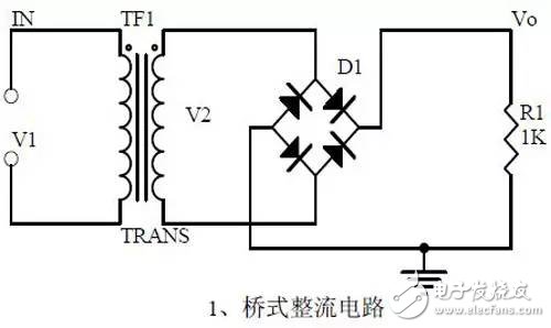
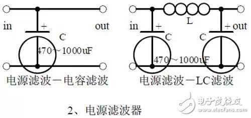
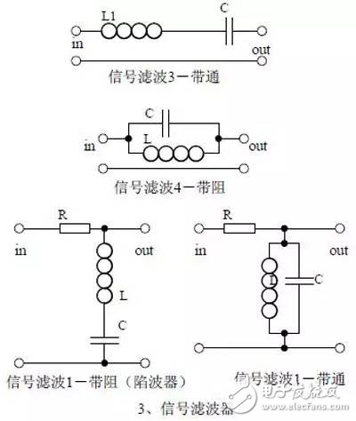
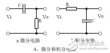
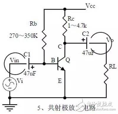
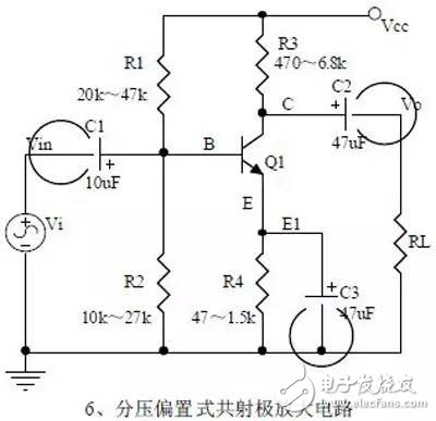
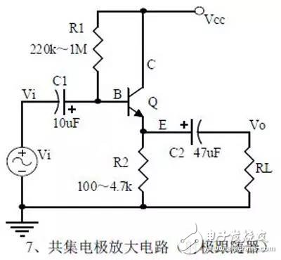
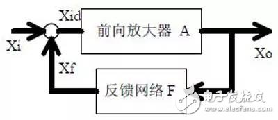
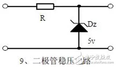
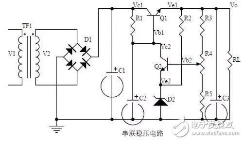
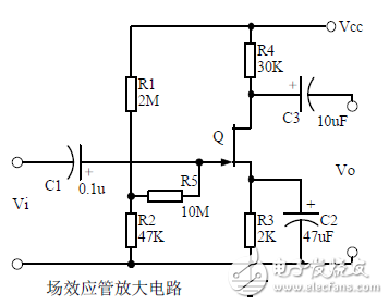
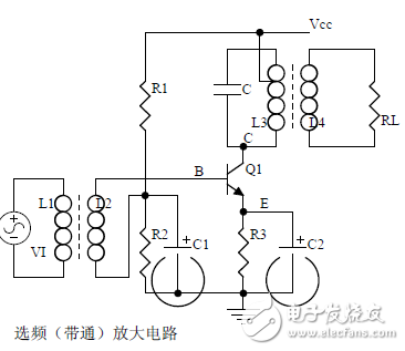
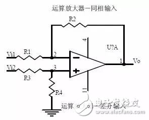
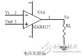
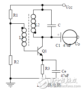
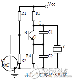
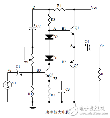
introduction The mastery of analog circuits is divided into three levels. The primary level is to skillfully remember these twenty circuits and to understand the role of these twenty circuits. As long as it is an electronic enthusiast, as long as people who are learning automation, electronics and other electronic control professionals should be able to remember these twenty basic analog circuits. The intermediate level is capable of analyzing the functions of the key components in the twenty circuits. What is the influence of the function of the circuit when each component fails, the variation of the parameters during measurement, and the handling of the faulty components; qualitative analysis The flow direction and phase change of the circuit signal; qualitatively analyze the change process of the signal waveform; qualitatively understand the magnitude of the input and output impedance of the circuit, and the relationship between the signal and the impedance. With this circuit knowledge, you are very likely to grow into an excellent maintenance and repair technician for electronics and industrial control equipment, and may be on the way to power supply design. The advanced level is to quantitatively calculate the input and output impedance of the twenty circuits, the ratio of the output signal to the input signal, the relationship between the signal current or voltage in the circuit and the circuit parameters, the amplitude and frequency relationship of the signal in the circuit, and the phase-frequency relationship. Characteristics, selection of component parameters in the circuit, etc. After reaching the advanced level, as long as you are willing, respected high-paying careers - power supply R&D engineers, electronic engineers, hardware engineers. Circuit 1, bridge rectifier 1. Unidirectional conductivity of the diode: Voltammetric characteristic curve: Ideal switch model and constant voltage drop model: 2. Bridge rectifier current flow process: Input and output waveforms: 3. Calculation: Vo, Io, diode reverse voltage. 1. Process analysis of power supply filtering: Waveform formation process: 2. Calculation: The capacity and withstand voltage value of the filter capacitor are selected. 1, the role of the signal filter: the difference and the same point with the power filter: 2. Impedance calculation, amplitude-frequency relationship and phase-frequency relationship curve of LC series and parallel circuits. 3. Draw a passband curve. Calculate the resonant frequency. 1, the role of the circuit, and the difference between the filter and the same point. 2. Analysis of the voltage change process of the differential and integral circuits, and draw a waveform diagram of the voltage change. 3. Calculation: time constant, voltage change equation, selection of resistance and capacitance parameters. 1. The structure of the triode, the current relationship of the poles of the triode, the characteristic curve, and the amplification condition. 2, the role of components, the use of the circuit, voltage amplification, input and output signal voltage phase relationship, AC and DC equivalent circuit diagram. 3. Calculation of static working point and calculation of voltage amplification factor. 1, the role of components, the use of the circuit, voltage amplification, input and output signal voltage phase relationship, AC and DC equivalent circuit diagram. 2. Analysis of current series negative feedback process, negative feedback on circuit parameters. 3. Calculation of static working point and calculation of voltage amplification factor. 4. Analysis of the equivalent circuit of the controlled source. Circuit seven, common collector amplifier circuit (emitter follower 1, the role of components, the use of the circuit, voltage amplification, input and output signal voltage phase relationship, AC and DC equivalent circuit diagram. The input and output impedance characteristics of the circuit. 2. Analysis of current series negative feedback process, negative feedback on circuit parameters. 3. Calculation of static working point and calculation of voltage amplification factor. 1. The concept of feedback, positive and negative feedback and its judgment method, parallel feedback and series feedback and its judgment method, current feedback and voltage feedback and its judgment method. 2. Amplification gain with a negative feedback circuit. 3. Negative feedback affects the amplifier's amplification gain, passband, gain stability, distortion, input and output resistance. 1. Characteristic curve of Zener diode. 2. Precautions for the application of Zener diodes. 3. Analysis of the voltage regulation process. 1. Block diagram of the series stabilized power supply. 2, the role of each component; analysis of the voltage regulation process. 3. Output voltage calculation. 1, the role of the various components of the circuit, the use of the circuit, the characteristics of the circuit. 2. Analysis of the working principle of the circuit. How to amplify the differential mode signal and suppress the common mode signal. 3. Single-ended input and double-ended input of the circuit, single-ended output and double-ended output working mode. 1. Classification, characteristics, structure, transfer characteristics and output characteristic curves of FETs. 2. The characteristics of the field effect amplification circuit. 3. Application of field effect amplification circuit. Thirteen, frequency selection (bandpass) amplification 1, the role of each component: the characteristics of the frequency selective amplifier circuit: the role of the circuit: 2, the calculation of the characteristic frequency: the selection of the parameters of the frequency selection component: 3, the amplitude frequency characteristic curve: 1. The concept of an ideal operational amplifier: virtual short-circuit at the input of the op amp : virtual open circuit at the input of the op amp : 2. The main purpose of the op amp circuit with inverting input mode: the phase relationship between the input voltage and the output voltage signal is: 3 The gain expressions in the non-inverting input mode are: the input impedances are: the output impedances are: 1. Characteristics of differential input operational amplifier circuit: Uses: 2. Relationship between output signal voltage and input signal voltage: 1. The role of the voltage comparator: The working process is: 2. The input-output characteristic curve of the comparator : 3. How to form the hysteresis comparator: 1. The composition of the oscillating circuit : the role of the oscillating circuit : the phase condition of the oscillating circuit oscillating : the oscillation circuit and the balance amplitude condition: 2. The relationship between the RC circuit impedance and the frequency: the relationship between the phase and the frequency: 3. RC Phase condition analysis of the oscillating circuit: oscillating frequency: how to select components: 1. Analysis of oscillation phase conditions: 2. DC equivalent circuit diagram and AC equivalent circuit diagram: 3. Calculation of oscillation frequency: 1. Characteristics of quartz crystal : equivalent circuit of quartz crystal : characteristic curve of quartz crystal: 2. Characteristics of quartz vibrator: 3. Oscillation frequency of quartz crystal vibrator: 1. Working process of Class B power amplifier: Crossover distortion: 2. Composite rule of composite triode: 3. Analysis of working principle of Class A and Class B power amplifier : Analysis of bootstrap process: Characteristics of Class A power amplifier : Class A power amplifier Features: Self-healing Hydrogel Screen Protector
The Screen Protector has a self-healing technology that can automatically eliminate small scratches on the Protective Film within 24 hours. Significantly reduce dust, oil stains and fingerprint smudges, anti-scratch.
The Screen Protection Film is very suitable for curved or flat screens. The Soft Hydrogel Film perfectly matches the contour of your device. Will not affect any functions of the phone.
The Ultra-Thin Protective Film with a thickness of only 0.14mm uses 100% touch screen adaptive screen touch screen technology, complete touch screen response, high-tech technology makes the screen touch to achieve zero delay, ultra-thin material brings you "realism".
The Protection Film has excellent clarity and incredible toughness, providing a high level of clarity and a glass-like surface, highlighting the sharpness of the most advanced smartphone display images and bright colors.
If you want to know more about Self Repair Screen Protector products, please click the product details to view the parameters, models, pictures, prices and other information about Self Repair Screen Protector.
Whether you are a group or an individual, we will try our best to provide you with accurate and comprehensive information about the Self Repair Screen Protector!
Self-healing Protective Film, Self-repairing Screen Protector,Self-healing Screen Protector, Self-Healing Hydrogel Film,Hydrogel Film Screen Protector Shenzhen Jianjiantong Technology Co., Ltd. , https://www.jjthydrogelprotector.com