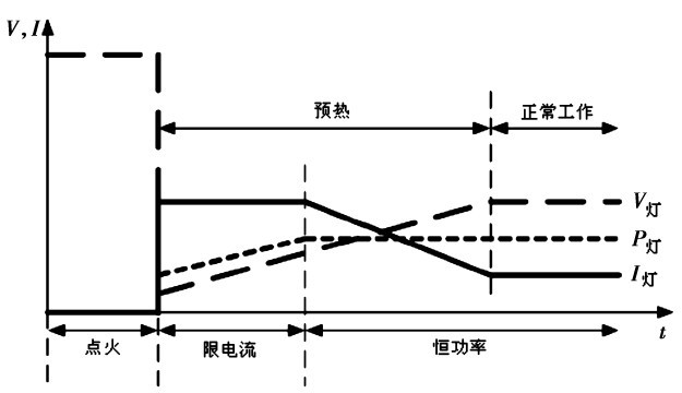
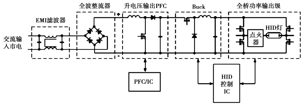
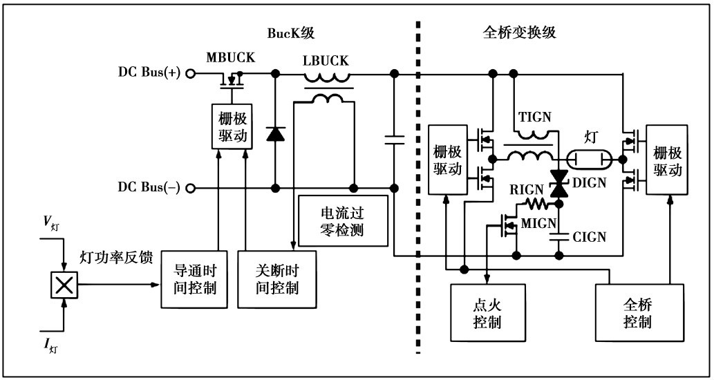
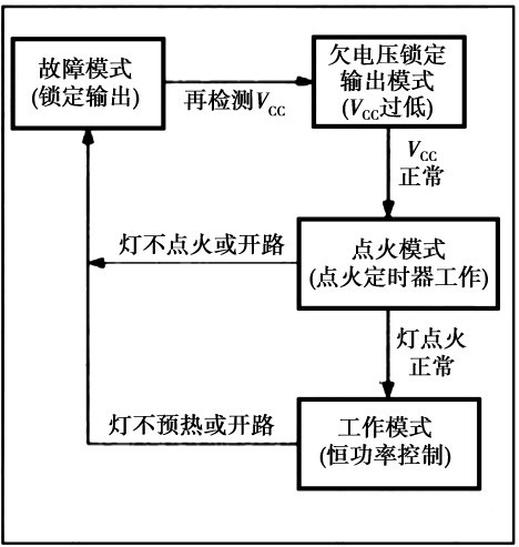
Abstract: The working principle and application of the electronic ballast circuit of 250 W metal halide lamp using IRS2573D are introduced. IRS2573D is a new control IC for HID lamp electronic ballasts introduced by IR. It has high integration and strong control functions. It is a dedicated ASIC integrated circuit for HID lamp electronic ballasts with different output power levels. Application. The HID lamp electronic ballast made up of IRS2573D has a series of advantages such as simple peripheral circuit and reliable operation. 1 HID lamp electronic ballast and related lighting market Commonly used HID lamps are metal halide lamps, mercury lamps and sodium lamps, which have the advantages of high working efficiency and large output power. The luminous efficiency of metal halide lamps is more than 100 lm/W, and the working life can reach 20 000 h. In the application, the working pressure inside the metal halide lamp is high, the spacing between the two discharge electrodes is small, and visible light is directly generated between the two discharge electrodes during operation. Today, HID is used in many outdoor lighting applications. Electronic ballasts for HID lamps require ignition, preheating, constant power control, power factor correction, and protection control for lamp loads and electronic ballast abnormal operating conditions. In practice, the design and control of HID lamp electronic ballasts is much more complicated than the design of fluorescent electronic ballasts. Table 1 shows the market annual compound growth rate (CAGR) comparison table of commonly used electric light sources on the market. It can be seen that HID lamps have a good application space in the home, commercial and industrial fields, while the application prospects of incandescent lamps and tungsten halogen lamps are not I am optimistic. Table 1 Market annual compound growth rate (CAGR) of lamp products from 2007 to 2015 2 HID lamp working process The HID lamp has four main working phases, namely breakdown, glow discharge, glow discharge to arc discharge and arc discharge. (1) Breakdown: The HID lamp is open for operation before the HID lamp is ignited. When the applied voltage is greater than the breakdown voltage of the HID lamp, the ions in the HID lamp generate an avalanche phenomenon, and the internal gas is ionized. At this time, the HID lamp voltage drops rapidly, but the HID lamp voltage is still greater than the rated working voltage, and the discharge current starts in the lamp. produce. (2) Glow discharge: During the glow discharge, the HID lamp voltage drops rapidly, and the HID lamp current rises rapidly. The glow discharge phase lasts for a very short time, and the HID lamp emits an unstable low light. (3) Glow discharge to arc discharge: The glow discharge to arc discharge is the main temperature heating phase of the HID lamp. At this stage, the HID lamp voltage is less than the rated working voltage, and the HID lamp current is greater than the rated operating current, with HID. As the lamp operating temperature rises, the lamp voltage gradually increases and the lamp current gradually decreases. Finally, the HID lamp voltage reaches its normal operating voltage (typically around 100 V) and the lamp power reaches its normal value. This phase is a short transition phase. (4) Arc discharge stage: After entering the arc discharge stage, the arc between the lamp electrodes tends to be stable, and the lamp enters a stable working state. The lamp current, lamp voltage and lamp power operating characteristics of HID are shown in Fig. 1. Figure 1 Lamp voltage, lamp current and lamp power operating characteristics of HID lamp ignition, warm-up and operating modes Through the control of the electronic ballast, the relevant technical requirements for preheating, starting and normal operation of the HID lamp can be met. Technical requirements for electronic ballasts for 3 250 W metal halide lamps The metal halide lamp requires an ignition voltage of up to 3 ~ 4 kV (typ) when used (the ignition voltage is greater than 20 kV if the metal halide lamp is in the hot ignition state), and the metal halide lamp needs to go through the warm-up period. Control loops such as current limiting and constant power output control during normal operation. The operation of the metal halide lamp requires strict control of the lamp power to ensure the consistency of the color and brightness of each metal halide lamp. Moreover, the driving power of the metal halide lamp is a low-frequency AC voltage (the typical low-frequency AC driving voltage operating frequency is not more than 200 Hz) to avoid the migration of mercury during the operation of the metal halide lamp and to avoid the problem of acoustic resonance, in the case of acoustic resonance. Will cause damage to the metal halide lamp. The main technical requirements for the normal operation of a 250 W metal halide lamp are as follows: (1) Output power during normal operation: 250 W; (2) Normal working lamp voltage: 100 Vrms; (3) Normal working lamp current: 2. 5 Arms; (4) Warm-up time: not less than 2. 0 s; (5) Lamp ignition voltage: 4 000 Vpk. The following describes the technical requirements and control methods of the electronic ballast for metal halide lamps using IRS2573D, and gives the working principle diagram of the circuit. Circuit operation principle of 4 250 W metal halide lamp electronic ballast The block diagram of the typical circuit operation of the metal halide lamp is shown in Figure 2. The EMI filter in the figure blocks the interference of the grid generated by the operation of the electronic ballast and the high frequency interference signal of the grid to the electronic ballast. Interference. The full-wave bridge rectifier circuit is used to convert the AC input mains to DC power, the boost voltage output active power factor correction circuit is used to achieve power factor correction, and the DC output bus voltage is stabilized. The buck output Buck converter is used to control the gold. The operating current of the halogen lamp, the full-bridge power output stage provides driving power for the metal halide lamp load, completes the ignition of the metal halide lamp, and enables the metal halide lamp to work normally. Figure 2 Block diagram of the typical working principle of metal halide lamp electronic ballast The Buck converter in the circuit shown in Figure 2 is used to control the operating current and lamp power of the metal halide lamp, and the Buck converter also converts the DC high voltage output from the output voltage of the active power factor correction circuit to a metal halide. The lower-level full-bridge converter DC supply voltage for lamp operation supplies power to the lower-level full-bridge output stage. The Buck converter operates in a current continuous conduction mode (CCM) or a current critical conduction mode (CRM), depending on the operating state of the lamp load. Figure 3 shows the block diagram of the circuit operation of the Buck transform stage and the full bridge transform stage. During the warm-up period of the metal halide lamp, once the metal halide lamp is ignited, the lamp voltage of the metal halide lamp is very low, but the operation of the metal halide lamp The current is very large, and the conduction time of the Buck converter is controlled by the feedback control loop, thereby completing the control of the working current of the metal halide lamp. During the stable operation of the metal halide lamp, the control of the Buck converter is controlled by the control function of the lamp power feedback loop. The pass time (as shown in Figure 3, the lamp power output signal of the multiplier) completes the lamp power control of the metal halide lamp. During the warm-up operation of the metal halide lamp, the Buck converter's current continuous conduction mode (CCM) allows for greater operating current for the metal halide lamp in the event that the Buck inductor is not saturated. Figure 3 Block diagram of the circuit operation of the Buck transform stage and the full bridge transform stage Assuming that the 400 V input DC voltage of the Buck converter remains constant (ie, the 400 V output voltage of the boost voltage output active power factor correction circuit remains constant), taking the normal operating frequency of the Buck converter to 70 kHz, the parameters of the Buck inductor can be Calculate using the following formula: The full-bridge conversion circuit provides the required lamp current and lamp voltage for the metal halide lamp. The typical operating frequency of the full-bridge conversion circuit is 200 Hz, and the pulse duty cycle is 50%. In the ignition control circuit shown in Figure 3. The bidirectional trigger diode DIGN is used to generate the 4 kV ignition pulse voltage required for ignition of the metal halide lamp. The ignition circuit is triggered by the conduction of MIGN. The discharge time constant of the RC loop is determined by the resistor RIGN and the capacitor CIGN. When the voltage across the bidirectional trigger diode DIGN reaches its trigger threshold voltage VDIAC, the bidirectional trigger diode DIGN breaks down and an ignition pulse voltage is generated at the primary winding of the ignition pulse transformer TIGN, thereby raising the secondary voltage at the ignition pulse transformer TIGN. The winding produces the 4 kV ignition pulse voltage required to ignite the metal halide lamp. Here, an ASIC control integrated circuit IRS2573D is used to control the Buck conversion stage and the full bridge output stage, and complete the control of several working modes of the metal halide lamp to make the metal halide lamp work normally. The working state diagram of the IRS2573D is shown in Figure 4. Figure 4 IRS2573D working state diagram Inside the IRS2573D contains a 600 V high-side gate drive output circuit with Buck converter control, full-bridge converter control, lamp voltage and lamp current detection, lamp power and lamp current feedback control loop, and Buck converter stage (BUCK pin). With cycle-by-cycle overcurrent protection control (CS pin), the on-time of the Buck switch is controlled by the lamp power control loop (PCOMP pin) or the lamp current limit loop (ICOP pin), and the Buck switch is turned off. The time is controlled by the inductor current zero-crossing detection input (ZX pin) control signal in the critical conduction mode or by the shutdown timing input signal (TOFF pin) in continuous conduction mode (CCM). The IRS2573D also integrates a 600 V full-bridge high- and low-side driver circuit. The operating frequency of the full-bridge circuit is determined by the component parameters connected to the external timing pin (CT pin). The lamp current and the lamp voltage are sampled (VSENSE and ISENSE pin) The signal obtained after multiplication can reflect the lamp power. The ignition timing output signal (IGN pin) drives the ignition control of the on/off completion lamp of the external ignition MOSFET (as shown in Figure 3). The ignition circuit consists of a MOSFET (MIGN), a bidirectional diode (DIGN), a capacitor (CIGN), a resistor (RIGN), and an output boost ignition transformer (TIGN). The ignition timing is determined by the parameters of the external (TIGN pin) component. The conduction and cut-off time of the ignition circuit. At the same time, a programmable fault timer (TCLK pin) is also integrated inside the IRS2573D to set the fault duration that can be used to shut down the IRS2573D under various fault conditions. These faults such as lamp ignition failure, lamp warm-up failure, lamp life termination, lamp arc instability, lamp output circuit open or short circuit, etc. The IRS2573D contains the relevant control functions required for the HID lamp electronic ballast circuit. The circuit diagram of the Buck transform stage and the full bridge conversion stage of the 250 W metal halide electronic ballast using the IRS2573D is shown in Figure 5. Figure 5 Circuit diagram of the Buck transform stage and the full bridge transform stage 5 Summary Due to the energy saving, long working life and high output power of HID lamps, HID lamps have been widely used in road lighting and indoor lighting applications. However, the design of HID lamp electronic ballasts is a more complicated task. Since the circuit uses the HID lamp electronic ballast ASIC IRS2573D and uses a three-stage circuit structure (APFC, Buck conversion stage and full bridge conversion stage), the design of the electronic ballast circuit of the HID lamp is greatly simplified. The circuit can be applied to metal halide lamp electronic ballast circuits of different power levels with slight modifications as needed. Shengtian New Energy (Shenzhen)Â Co., Ltd. , https://www.stenergysolar.com

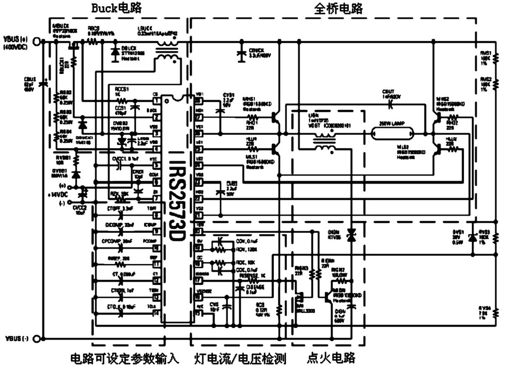
250W metal halide lamp electronic ballast circuit using IRS2573D
8 times
Window._bd_share_config = { "common": { "bdSnsKey": {}, "bdText": "", "bdMini": "2", "bdMiniList": false, "bdPic": "", "bdStyle": " 0", "bdSize": "24" }, "share": {}, "image": { "viewList": ["qzone", "tsina", "tqq", "renren", "weixin"], "viewText": "Share to:", "viewSize": "16" }, "selectShare": { "bdContainerClass": null, "bdSelectMiniList": ["qzone", "tsina", "tqq", "renren" , "weixin"] } }; with (document) 0[(getElementsByTagName('head')[0] || body).appendChild(createElement('script')).src = 'http://bdimg.share. Baidu.com/static/api/js/share.js?v=89860593.js?cdnversion=' + ~(-new Date() / 36e5)];