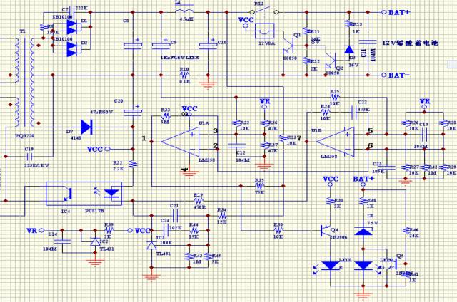
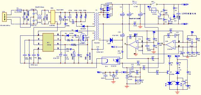
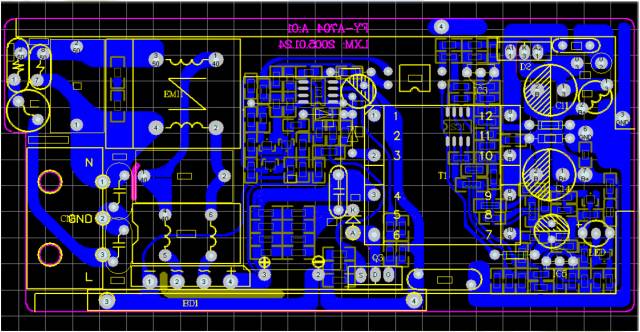
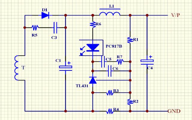
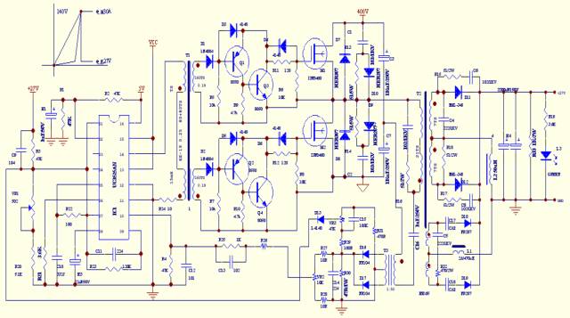
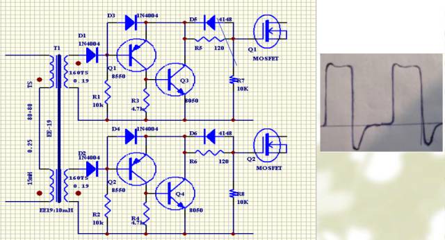
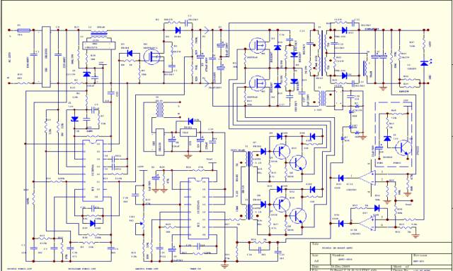
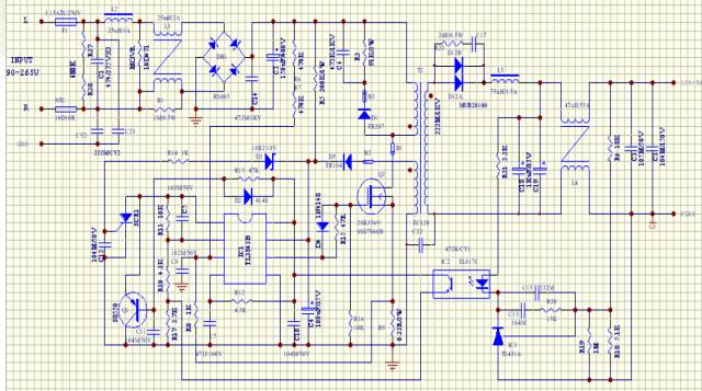
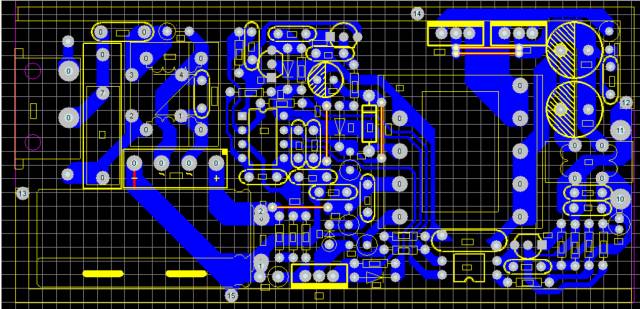
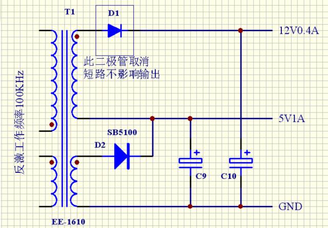
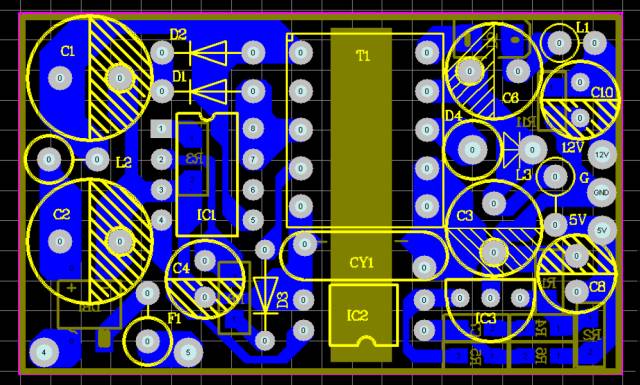
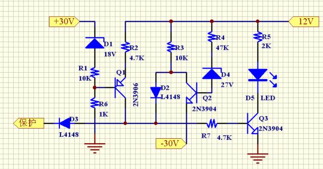
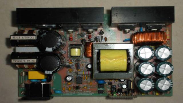
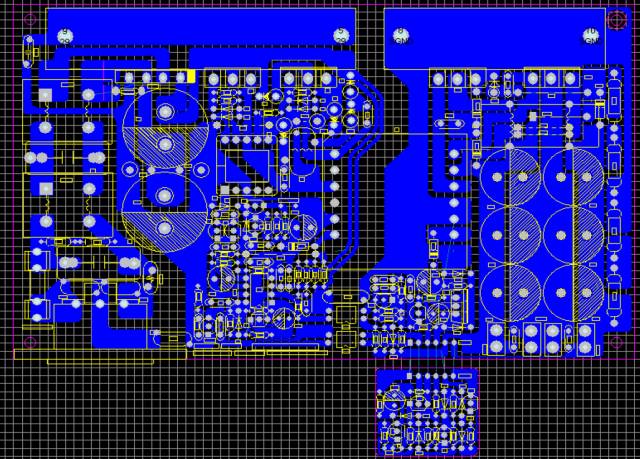
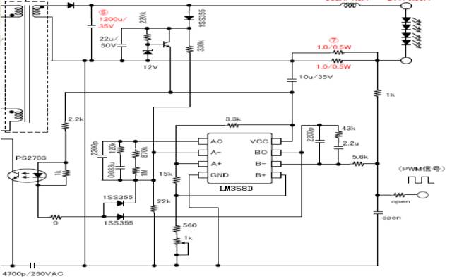
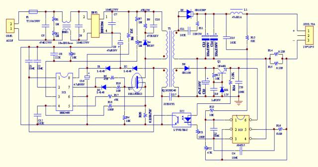
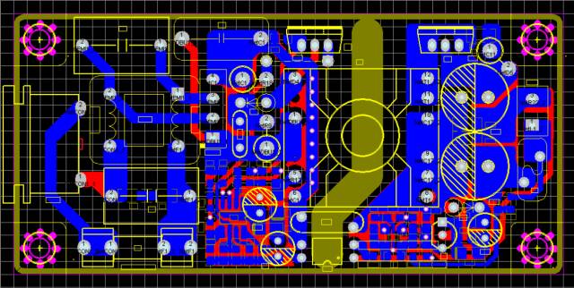
Application examples (1): A simple three-section lead-acid battery charger control circuit A simple three-section lead-acid battery charger control circuit This PCB file is a 12V/4A simple three-stage charger designed by the principle of the above figure (without relay circuit). Application examples (2) Simple single TL431 current limiting and constant voltage control method â—When the current increases, the potential of TL431-1 is too high, so as to function as the current current. Because of the existence of R3, the output voltage is compensated. Therefore, the current limiting and stabilizing function can basically be integrated, and it has a relative Cost advantage. Application examples (3) A low-voltage xenon lamp power supply starting circuit â—This circuit is a half-bridge circuit that limits the output power. It uses a capacitor to limit the current. (Adjust VR2 to get different starting voltage values, and adjust VR1 to get different output currents to match different low-voltage xenon lamps). â—Output two windings, the first is the main winding capable of providing 27V30A, the second is capable of providing 140V starting voltage, and the capacitor connected in series in front of the rectifier diode limits the starter current â—Because the series capacitor limits the current to achieve synchronous start, the circuit must work at a fixed frequency, and the input voltage range cannot be too high. Generally, changes within 5% will not affect the normal operation of the xenon lamp. â—The characteristic of this circuit is to effectively solve the problem of synchronous start, and realizing natural synchronization is more reliable than software control. â—The starting characteristic of the xenon lamp is that it must be completely synchronized, and it cannot be started if the voltage is low. But once the current is started, the voltage must be reduced to 24V-28V while the current is up. If it is too high, the lamp will explode, and the current will be extinguished if the current is lower than 25A. It cannot be restarted immediately after being turned off. The application of this method can meet the requirements effectively and at low cost. Application examples (4) A transformer isolation drive circuit with ideal waveform Application example of transformer isolation drive with ideal waveform Application examples (5) Recommendations for the design of flyback switching power supply for small transformers. This case is the full voltage input of the EC-2828 transformer and the output power is 60W. EC-2828 transformer has full voltage input and output power is 60W. â—For the design of small magnetic core transformer: The main problem is that the area of ​​the magnetic core Ae is too small, which will cause the phenomenon of too many primary turns. The working frequency can be appropriately increased. The working frequency in this case is 70KHz-75KHz. Because the number of turns is too large, the coupling of the primary and secondary will be more advantageous. Therefore, the VCC winding voltage will rush to a relatively high state at the moment of short circuit. In this case, there is a thyristor for overvoltage protection in the schematic diagram. Then, the short circuit of the secondary winding is coupled to the VCC winding to reduce the voltage so that the IC cannot start. This process can be realized. â—To achieve the above characteristics: VCC winding wire diameter must be small, I personally generally take it below 0.17mm, less than 0.12 will easily break. Such a small wire diameter is not about saving copper, but the impedance of the copper wire can be used to replace the function that many designers are used to connecting small resistance resistors in series with the VCC rectifier diode, and this uses the impedance of the coil itself to suppress AC In this case, it is more effective, which can prevent the effect of the subsequent circuit from being damaged by the instant impact. â—The primary and secondary main windings must be the nearest adjacent windings, so the coupling will be more advantageous. â—The interference generated by the switching power supply when the MOSFET-D terminal is working is the largest (it is also the terminal where the RCD absorption terminal is connected to the transformer). It is recommended to wind it around the first winding of the transformer as the starting point when winding the transformer. Let him hide in the innermost layer of the transformer, so that the shielding of the back winding copper wire has a better interference suppression effect. â—When calculating the number of turns of the VCC winding, try to multiply the lowest working voltage of the IC by 1.1 times as the error value. There is no need to consider the voltage drop of the copper wire, because the current before starting is very small, so this resistance does not have much influence, almost Can be ignored. Before the circuit is started, the voltage on the capacitor on the VCC can be charged to the starting voltage of the IC due to the charging of the high-voltage end start resistor. Once the circuit has a problem, it will not start VCC because the preset value of the winding voltage is low. The circuit also won't start, and it usually shows a hiccup state. â—Why should the value be selected according to the low end of the IC's working voltage? Because our secondary winding is wound adjacent to the primary winding, the coupling effect is relatively best. We do the short circuit test as well as the output short circuit of the secondary, because the coupling effect is good, VCC will decrease rapidly after a short overshoot when the secondary is shorted, and the circuit is best protected when it drops to the off voltage of the IC. It should be noted that this voltage needs to be 1V higher than the saturated conduction of the MOSFET to avoid insufficient drive. â—It is also beneficial to reduce the power consumption of the IC itself. Whether it can increase the life of the IC cannot be verified, but the stability should be higher. Application examples (6) A relatively stable solution for dual flyback outputs Dual flyback output circuit with relatively stable output â—This circuit is generally used in low-power power supplies. In order to ensure that the cross adjustment rate of the two windings is better. We need to pay attention to some issues. â—In this example, we generally set 5V as the sampling feedback terminal. If the double-channel sampling cross-adjustment rate may be worse, it can't even separate no-load and independent load problems. This method can solve this problem, this method is not It is suitable for applications where the two sets of voltages are far apart. It will take up one foot of the transformer. â—Feedback optocoupler power supply uses 12V power supply, and the sampling point is better before the back-stage filter inductor. Because the fluctuation in front of the filter inductor reflects the modulation state of the front-end PWM more quickly, even if the TL431 is turned on to a certain degree, because the fluctuation of 12V can make the current feedback on the optocoupler have a slight difference, in a certain situation in the feedback loop Next, the selection of the optocoupler power supply sampling point is more conducive to the balance control of dynamic response and adjustment rate. â—The 12V winding should be placed closer to the primary winding. This is more effective to ensure that the 12V voltage change ratio is smaller, because we are feedback sampling the 5V terminal, so the 12V winding is difficult to control. Combining these can better control the balance of the two windings. Although it cannot be absolutely good, it has certain reference value in relative terms. â—The model mentioned on the previous page can basically control the error within the range of +/-5%, which is within the acceptable range. Friends who like to try it out are recommended. Application examples (7) Positive and negative output power supply undervoltage short-circuit voltage protection control circuit applied to power amplifier Description: Power amplifier power supply positive and negative dual output voltage protection â—Q1 constitutes a positive voltage undervoltage short-circuit protection circuit â—When the positive voltage is short-circuited, the voltage is reduced by the Voltage Regulator diode and divided by the Q1 drive voltage divider resistor, then Q1 is turned on, and the protection signal can be sent. â—Q2 constitutes a negative voltage undervoltage short-circuit protection circuit â—When the negative voltage is short-circuited, the voltage rises to the Zener diode in series with the base of Q2, and when Q2 is turned off, the voltage signal on the collector of Q2 can send a protection signal through D2. â—Q3 is the indicator light drive circuit as a protection. â—In practical applications, this circuit needs to delay the process of positive and negative voltages for the power supply VCC from boot to normal startup, otherwise there will be a protection signal when booting, resulting in failure to boot normally. If you need to lock up, you can use the output protection signal to drive a thyristor lock-up circuit composed of a triode. Power amplifier power supply PCB with positive and negative dual output voltage protection Application examples (8) Using LM358 to Realize Current Limiting and Voltage Stabilization PWM Dimming Control at LED Output â—The application of this example is to directly add the PWM signal to the current sampling signal, and modulate the time of the over-current protection signal by adjusting the width of the PWM to adjust the current limit. â—The thing to note is that PWM requires inverting input, which means that the smaller the duty cycle, the greater the current applied to the LED. The larger the duty cycle, the smaller the LED current. Application examples (9) A 50W LED drive circuit with power factor compensation 50W LED driver PCB with power factor compensation Modified Sine Power Inverter,Sine Wave Vs Square Wave Inverter,Modified Sine Wave Power Inverter,Modified Sine Wave Inverter zhejiang ttn electric co.,ltd , https://www.ttnpower.com