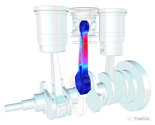
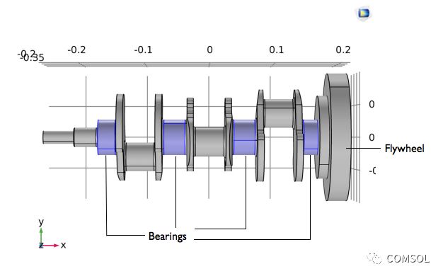
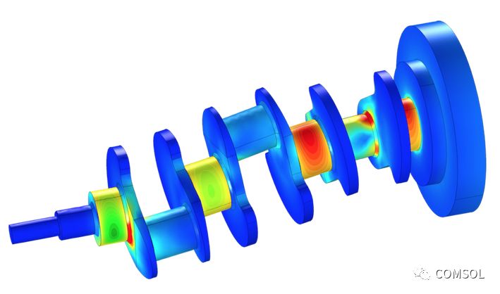
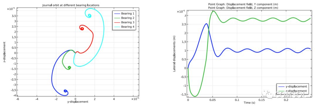
The crankshaft of a reciprocating engine can generate self-excited vibrations during rotation due to the eccentricity of the crank pin and the counterweight on the mechanical part. In this article, we will use the "Rotor Dynamics Module" to accurately study the response of the rotor and the orbit of the on-axis balancer, which is an add-on to the COMSOL Multiphysics® software and the Structural Mechanics Module. Engineers can improve crankshaft design based on simulation results to reduce vibration and optimize engine performance. Analyze the various components in a reciprocating engine Reciprocating engines are currently the mainstream engines in the automotive industry. Failure of one part in the engine may cause the entire engine to fail. A previous article emphasized this factor when analyzing the fatigue of reciprocating engine connecting rods. In optimizing the engine design through fatigue analysis and extending its working life, we also need to include other engine parts in the analysis. Prediction of Fatigue Life of Three-cylinder Engine Reciprocating Connecting Rod. We discuss the engine crankshaft as an example. This mechanical part drives the piston connected to it to reciprocate and converts reciprocating motion into rotational motion. According to the design intent, the crankpin (sometimes called the crankshaft neck) deviates from the axis of rotation, making the transition between the two types of motion possible. However, when the crankshaft rotates, eccentricity of the crank pin generates centrifugal force. In order to balance these forces, people add some masses or weights to the crankshaft. However, an unbalanced bending moment is produced along the length due to the axial offset of the balance weight on the crank pin. Therefore, we must choose the position of the balance quality in order to minimize the unbalanced bending moment, or balance the rotor. The eccentricity of the crankpin and balance weight and their axial displacement may cause the crankshaft to experience self-excited vibration when it rotates. Other machines with rotating parts are no exception. These vibrations affect the safety and performance of individual parts and the entire equipment system. The latest "Rotor Dynamics Module" provides professional functions to facilitate accurate vibration analysis of the crankshaft of the engine. In the following, we will discuss one case in the “case download†showing related features. Model Case: Rotor Dynamics Analysis of the Crankshaft Let's take a look at the geometry of the model. In this example, we used a crankshaft in a three-cylinder reciprocating engine. The structure of the crankshaft is shown in the figure below. The picture highlights the position of the flywheel and the bearing. Engine crankshaft geometry. The analysis assumes that the rotor only experiences self-excited vibration caused by the eccentric mass, ignoring the load of the piston acting on the crank pin. In order to reduce high frequency vibrations, material damping is applied to the rotor. In steady state, the angular speed of the crankshaft is 3000 rpm. However, initially increase the angular speed gradually in a ramp manner to ensure a smooth start. The example ramp length ensures that the rotor angular speed can increase linearly from 0 rpm to 3000 rpm in one revolution, and then the rotor continues to operate at an angular speed. To accurately simulate a crankshaft-bearing package system, we can use a solid rotor coupled to a hydrodynamic bearing for multiphysics coupling. The coupling includes: Solid rotor physical field node Hydrodynamic bearing node Solid rotor bearing coupling Multiphysics node We can use the hydrodynamic journal bearing feature in the hydrodynamic bearing interface to analyze the thin fluid film inside the journal bearing. Evaluate simulation results The following figure shows the stress distribution of the crankshaft. As the drawing shows, near the flywheel position, the bearing is subjected to the greatest load and the greatest stress is generated in the corresponding journal. Bearings close to the flywheel also bear the highest pressure. Crankshaft stress and bearing surface pressure distribution. Careful observation shows that the bearing journals of the four bearings are very stable. In the steady state, each journal reaches its own equilibrium position. The lower left plot fully illustrates this point. The lower right plot analyzes the lateral displacement component of the third journal. The results show that the lateral displacement is subjected to a damped vibration and reaches an equilibrium value in a steady state, consistent with the above. Left: The plot shows the trajectory of the bearing journal center. Right: The plot shows the lateral displacement component of the third journal. Learn more about rotor dynamics A quick look at the "Rotor Dynamics Module" and its various features and functions can be found in this article: Using Rotor Dynamics Modules to Analyze Rotating Machinery of Various Types View archived webinars to learn how to use the "Rotor Dynamics Module" function: Analyze rotors and rotating parts using COMSOL® software
Indoor Fixed LED Display is a popular product for its high quality, every year sold to at least 80,000 pieces around the world, including Europe, North America, southeast Asia.Compared to other indoor LED display in the market, its biggest advantage is that it can display high-definition images while maintaining low power consumption.Besides, it adopts Die casting aluminum cabinet which is ultra-thin and ultra-light and owns good heat dissipation.Easy to install and maintain and suitable for multiple indoor scenes.
Application:
Movie theaters, clubs, stages.
Indoor Fixed LED Display,Led Wall Display,Video Wall Display,Outdoor Led Screen Display Guangzhou Chengwen Photoelectric Technology co.,ltd , https://www.cwledpanel.com


* Business Organizations:
Supermarket, large-scale shopping malls, star-rated hotels, travel agencies
* Financial Organizations:
Banks, insurance companies, post offices, hospital, schools
* Public Places:
Subway, airports, stations, parks, exhibition halls, stadiums, museums, commercial buildings, meeting rooms
* Entertainments: