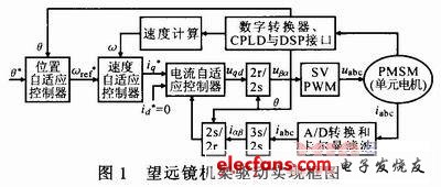
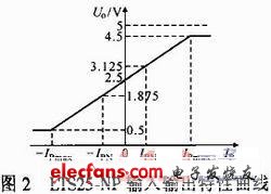
At present, the commonly used transmission methods of astronomical telescopes are mainly worm gear transmission, gear transmission, friction transmission, and direct drive. The direct drive telescope frame is adopted here, and the combined arc AC PMSM is adopted. Direct drive directly couples the motor and the load, which improves the reliability of the system, but puts forward higher requirements for the smooth operation of the motor itself and ultra-low speed. The current loop occupies an important position in the servo drive system and directly determines the quality of the servo system. Many literatures have studied the current sampling. The current loop is the inner loop of the telescope drive control system. The accuracy and speed of current sampling directly affect the calculation accuracy of the entire current loop, which has a major impact on the tracking and tracking performance of the telescope frame. The design of the current loop is to ensure the speed accuracy of the telescope tracking target And the key part of torque stability. Here, a current sampling circuit based on a single power supply is designed, and TMS320F2812 is used to realize the A / D conversion of the current sampling link, which provides convenience for the subsequent controller design. 2 Design of rack drive current sampling circuit The arc AC PMSM is used, the stator diameter is 2.5 m, the rotor diameter is 2.2 m, 15 groups of stator units, 60 pairs of magnetic poles constitute the rotor, each group of stator units and 4 pairs of rotors form an arc AC PMSM, It consists of 15 sets of unit motors. Any one of the unit motors can work independently or with several of them. A 2.5 m direct drive motor can drive a telescope with a caliber of 4 m. Motor parameters: rated power 3 kW; rated voltage 380 V; rated current 12 A; rated frequency 0.533 Hz; rotational inertia 262.74kg · m2; rated speed 4 r · min-1; stator resistance 33 Ω; pole pair number is 60. At present, the commonly used controllers are digital systems such as single chip microcomputer, ARM and DSP. The current output by the motor is an analog signal. Here, the TMS320F2812 is selected for A / D conversion. The current sampling circuit is TLV2374 powered by a single power supply. According to the motor parameters, the current sensor uses LTS25-NP. 2.1 General block diagram of telescope rack drive implementation The designed current detection circuit passes the three-phase stator current of the arc AC PMSM through the current sensor and enters the A / D port of the DSP to convert it into a digital signal, which is convenient for the signal processing of the controller and the inverter. Since the stator winding of the arc motor adopts the Y connection method, there is ic = ia + ib, so only two phase currents need to be detected to obtain the three-phase current. To achieve high-performance closed-loop control of AC PMSM, the current feedback link is indispensable. Only by detecting the current of the stator winding can it provide the basis for the realization of the inverter link, that is, the SVPWM algorithm. According to the working principle of PMSM, the accuracy and real-time performance of stator current detection is the key to determine the accuracy of the entire vector control system. For precision arc motors, the closed loop is the preferred control method to ensure the tracking target and image quality when driving the telescope, which can achieve high-precision, high-performance transmission and servo control. In addition, a complete and reliable drive system includes overvoltage, undervoltage, overcurrent protection and other fault detection and protection circuits in hardware. These circuits need to detect the voltage and current signals of the motor. The arc AC PMSM drive system is composed of a position loop, velocity loop, and current loop. Figure 1 shows the general block diagram of the telescope frame drive implementation. 2.2 TLV2374 current sampling circuit design The TLV2374 device is a single-supply operational amplifier with rail-to-rail input and output capabilities. The minimum operating supply voltage is 2.7 V. The rail-to-rail swing output feature provides a bandwidth of 3 MHz, requiring only 550 μA of operating current. The operating voltage can reach 16 V. After a long period of research and experiments, the detailed design process of the current sampling system powered by a single power supply is given here. The current sensor IXS25-NP used in the system is a sensor with a closed loop principle. The 5 V single power supply makes the design of the peripheral hardware circuit simpler, without the need to increase the voltage boost circuit, thereby reducing the interference of the power supply to the system. The current sensor has small temperature drift and high accuracy. The sampling resistor is built-in and is a voltage output. It avoids the situation that the accuracy is reduced due to the increase of the external sampling resistor and the op amp. The output characteristic curve is shown in Figure 2. As shown. There are three kinds of current sensor connection methods. According to one of the connection methods, the output voltage range of the current sensor is 1.9 to 3.1 V. The voltage in this range cannot be directly sent to the DSP A / D (0 to 3 V) for conversion. , And the voltage range is too small, it will inevitably reduce the conversion accuracy of the A / D converter. In order to make full use of the A / D converter, according to the actual A / D conversion result, a current sampling circuit is designed to output the signal at full scale The range is adjusted to 0 ~ 2.8 V. Experiments show that exceeding 2.8 V will sometimes cause the output to be saturated. In order to prevent the circuit from damaging the A / D interface of the DSP under abnormal conditions, a limiting circuit is added to the circuit. Suppose the input of the sampling circuit is Uin, the range is 1.9 ~ 3.1 V, the output of the sampling circuit is Uo, the range is 0 ~ 2.8 V, and if the input and output are linear, then: Uo = AUin + B (1) According to the relationship between input and output, A = 7/3 and B = -133 / 30 are calculated, namely: Uo = 7Uin / 3-133 / 30 (2) It is known from Equation (2) that the essence of input and output is a subtraction circuit composed of an op amp, and a subtraction circuit composed of a single-supply op amp can be designed. Since the TLV2374 is powered by a single power supply, it can be seen that the power supply voltage is 5 V for the positive power supply and 2.5 V for the negative power supply. Here, a voltage reference chip is used and adjusted to obtain a 2.5 V reference voltage. If the output of the current sensor is Uin1, the 2.5 V reference voltage For Uin2, there are: Uo = 7Uin1 / 3-133Uin2 / 75 (3) Choose the appropriate resistor to realize the sampling circuit. Figure 3 is the detection sampling circuit of the current sensor. There are four levels of processing: the first level performs impedance transformation; the second level is the second-order active filter circuit; the third and fourth levels are the subtraction circuit calculated by the above formula, where, is Ensure that the input and output are in the relationship of formula (3), intentionally placing two 1/1 000 precision adjustable resistors in the proportional circuit section to adjust the linear relationship between the input and output. It should be noted that when using a single-supply op amp, the proportional gain is relative to the voltage at the same phase. In actual debugging, because the current signal from the sensor has higher harmonics and other interference signals, it is necessary to design a hardware filter to suppress it. The current detection circuit of the second-order low-pass filter designed by this system is located in the first place in the above situation. Level 2, considering the ultra-low speed of the precision arc motor, the cut-off frequency of the designed low-pass filter is 10 Hz, pay attention to the selection of the capacitance value, the capacitance at the inverting end is usually twice that of the capacitance at the in-phase end, and the current sampling circuit The specific implementation is shown in Figure 3. Conduction And Convection Dry Herb Vaporizers END GAME LABS,Conduction And Convection Dry Herb Vaporizers,Portable Dry Herb Vape,Dry Herb Vape Adapter END GAME LABS , https://www.eglvape.com

