A solenoid is a linear motor with a fixed operating range. Solenoids are suitable for simple switching applications and function much like relays. For example, they do this in the starter and door lock. This article refers to the address: http:// In summary, electronic control of the transmission simplifies design, increases reliability and reduces costs for electromechanical systems. The electronic transmission control system improves control of the transmission shift point, reduces the abrupt change of the transmission shift and improves the smoothness of the shift. In addition, the flexibility of electronic control is more adaptable to changing conditions. The electronic control of the shift point has fine resolution, which improves acceleration quality, saves cost, improves load control and reduces exhaust volume, thus making the driver the least. In addition, electronic control allows the transmission to shift smoothly to change load and acceleration. With electronic control systems, shift control algorithms other than shaft speed, vacuum and driver input may be affected by various input parameters. These parameters include prior spark, injector parameters, input speed sensor, line shift selection, engine speed, throttle position, torque converter speed and brake, automatic transfer fluid (ATF) temperature, engine temperature, wheel slip sensor And inertial sensors. Combined with these inputs, various shift optimization algorithms can be implemented to suit the overall operating conditions. In order to use these inputs most efficiently, the system must be optimized by precisely and infinitely adjusting the shift points and shifting speeds of the electronic control system. In electronically controlled automatic transmissions, hydraulic control is still used to change the transmission. Unlike mechanical control systems, electronic control of the liquid in the electromechanical system is achieved by a linear solenoid that changes the pressure of the liquid applied to the actuator of the clutch assembly. In order to accomplish this, it is of utmost importance to accurately and reproducibly control the open solenoid - allowing accurate and repeatable control of the shift point through accurate liquid flow during application. Determining the state of the solenoid The state of the linear solenoid is controlled by a feedback loop. For example, the down pressure of the valve can be monitored and used as a feedback signal to compare with the setpoint to adjust the duty cycle of the pulse width modulation (PWM) to control the solenoid, but measuring the down pressure can be difficult, impractical, or High cost. Another practical solution is to determine the state of the solenoid by measuring the current through the solenoid. This method is achievable because the force exerted by the mechanical load on the solenoid is directly proportional to the strength of the magnetic field, which in turn is directly proportional to the current through the coil. The proportional control of the solenoid is achieved by balancing the force between the spring-like load and the solenoid magnetic field, wherein the magnetic field strength can be determined by measuring the current of the solenoid. PWM solenoid control drives the solenoid by using a pulse width modulation (PWM) input signal generated by the microcontroller to quickly turn on or off the field effect transistor (FET) in series with the solenoid and voltage source (car battery) switch. The average voltage applied to the solenoid depends on the ratio of the 'on' time of the PWM waveform to the pulse period. Variations in pulse width and solenoid mechanical load can cause changes in the average current flowing through the solenoid. This average current indicates the total amount of movement of the solenoid, so it also indicates the fluid pressure and flow. For a particular PWM waveform, the relationship between solenoid motion and average current can be determined by the characteristic of the representation. Although the magnetic field strength is directly related to the current through the solenoid, the actual mechanical forces and motions are not strictly related because they also depend on the structure of the solenoid and the nature of the load. Therefore, it is necessary to use the representation characteristics to correlate the average current of the open solenoid. For example, when the solenoid is initially energized to overcome static friction, the PWM ratio must be increased. Once the static friction is overcome, it is necessary to drive it back and forth with a different PWM ratio. Low-End Current Detection Using High-End Drives The circuit in Figure 1 shows that the switch is connected to the high voltage side of the battery (not grounded) and in series with the solenoid coil and the grounded resistive shunt. A reverse diode is connected across the coil for clamping (eg, shorting) the induced voltage generated by the coil when the current is off. The use of the shunt as a reference allows the use of inexpensive op amps in electronic control units (ECUs) - common mode indicators are not important - to measure the voltage across the shunt. 2. Because the switch is placed on the high voltage side, the cost of purchasing and driving such a switch is relatively high. The PWM drive requires careful level shifting between the logic output of the microcontroller and the gate. High-End Current Detection with Low-Side Switches A better way to drive a solenoid is to use a ground-referenced switch (see Figure 2) to use a low-cost, low-side switch. Figure 2. ECU with low-side switch and high-end detection An important advantage of this drive method is that it can detect a short to ground because the high current will flow through the shunt - as shown in Figure 2. High Side Switch High Side Current Detection Figure 3 shows a configuration that minimizes the possibility of accidental solenoid activation and excessive corrosion, where both the switch and the shunt are connected to the high voltage side. When the switch is turned off, the battery voltage is removed from the solenoid, thereby preventing potential short circuit damage to the ground, and allowing the return current to be included in the measured value. When the switch is turned off, the battery voltage is removed from the load, thus eliminating the corrosive effects caused by the voltage difference. When using the high-side detection scheme of the low-side switch (see Figure 2), it is possible to measure the short circuit to ground because the solenoid current from the high-end is all passed through the shunt, as shown in Figure 3. Figure 5. Functional Block Diagram of the AD8200 Figure 5 shows the functional block diagram of the internal wiring of the AD8200. Before designing a differential amplifier with a cheap op amp and some external resistors, consider the performance required to accurately measure the solenoid current to meet the requirements of the control application, requiring an allowable error of less than 0.01%. A precision matching resistor is used to build this circuit. The AD8200 has laser trimmed resistors that meet the above accuracy requirements while handling both AC (AC) and DC (DC) operating voltages. It is available in a SOIC package with a typical offset drift and gain drift of 6 When the driver needs to increase the acceleration, this requirement is usually transmitted through a downshifting mechanism, including a lever that is connected from the throttle in the engine compartment to one end of the transmission. This lever drives a lever that blocks a series of passages in the throttle body. This forces the transmission to lower the gear at high accelerations until the governor quickly exceeds the downshifting mechanism. A vacuum regulator is used to accommodate the change in load. As the engine load increases, a change in vacuum causes a link to slide in or out of the valve body, thereby changing the shifting point and shifting speed of the transmission. Although the above method of controlling shifting points and shifting smoothness is effective, these parameters cannot be adjusted to accommodate more changing conditions because of the limitations of the mechanical system used to control them. Usb-C Hub 4 In 1,Usb C Hub Laptop Docking Station,Usb C Hub For Surface Book Wireless,Docking station for laptop,Docking station for macbook pro Shenzhen Konchang Electronic Technology Co.,Ltd , https://www.konchangs.com
Linear or proportional solenoids, on the other hand, can control their state in a very precise manner. They are used to manipulate pistons or valves in applications such as transmissions and fuel injections to accurately control fluid pressure or flow.
The transmission needs to accurately and smoothly control the pressure on the clutch to change the transmission and to control the lockout torque converter. Electronically controlled transmissions may include more than eight linear solenoids, all of which require smooth and accurate control. For common rail diesel fuel injection applications, with over 2000
The pressure at psi (pounds per square foot) may require a linear solenoid per cylinder - and the fuel pump requires a solenoid - to accurately adjust the pressure to ensure that the fuel flow is injected in a predetermined manner.
Application Example: Electronic Transmission Control The automatic transmission is a major electronic control system that replaces mechanical control because of the improved drive quality and fuel efficiency of the electronic control system. Previous improvements in fuel efficiency and acceleration have been due to the use of a lock-up torque converter. Recently, the combination of hardware and software using electronically controlled solenoids makes it easier to adjust the shifting algorithm, and it also has the added advantage of transmission shift stability and quality.
Measuring the current through the coil is an important indication of the state of the solenoid. The most efficient way to measure solenoid current is to measure the voltage across the resistive shunt in series with the solenoid, battery, and its switch. There are several different ways to configure this series circuit for switching and voltage measurement. 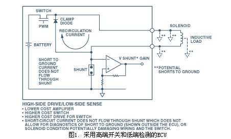
Figure 1. ECU with high-side switch and low-end detection
When considering this application, the design engineer must consider the following shortcomings:
1. The return current of the solenoid is not included in the above measurement, so the average current measured by the circuit through the solenoid coil is inaccurate. The return current of the solenoid can assist in detecting the normal state of the solenoid; if some coils begin to short-circuit, this short-circuit condition can be detected by measuring the controlled return current.
3. Additional circuitry is required to detect a short to ground because the short circuit current does not flow through the shunt. If a short to ground is not detected (see Figure 1), wiring and FET damage may occur.
4.
This measurement may be unstable, in fact, because "grounding" is not an ideal universal connection, it is represented by an inverted triangle. In practical applications, "grounding" may not be "grounding" in the actual sense. Therefore, the voltage drop caused by the current between the ground of the operational amplifier and the ground of the shunt can cause a large error.
This can significantly improve the measurement because the return current of the solenoid is included in the measurement. In addition, the drive cost can be reduced because there is no need to level shift the gate. 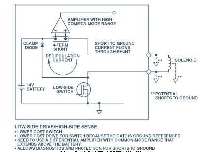
However, the amplifier must have a high common-mode rejection ratio and must be able to reject large common-mode voltages (CMV). In this example, the voltage value of the shunt varies from battery voltage to battery voltage plus diode drop. The reason for this is explained as follows: The common mode voltage of the shunt remains as the low impedance battery voltage when the switch is closed. When the switch is turned off, the voltage across the solenoid will reverse because of the inductive nature of the solenoid, causing the common-mode voltage to contain the clamped diode drop—although only transient current flows—before stabilizing to the battery voltage .
A major concern when using this current sensing method is that the high end of the battery is always connected to the solenoid. This can result in an unexpected solenoid switch if there is an intermittent short to ground. In addition, continuous application of voltage to the solenoid can cause excessive corrosion. 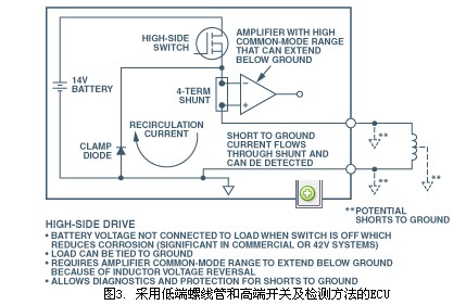
Figure 3. ECU with low-end solenoid and high-side switch and detection method
However, in this case, when the switch is turned off, the reverse voltage across the solenoid causes a large swing of the common-mode voltage, swinging from the high-side voltage of the battery to a voltage lower than the ground potential by a diode drop ( The reverse voltage is limited by the clamp diode). Therefore, the amplifier used in this application must be able to provide an accurate measurement of the shunt voltage (or current), ignoring the large rapid swing of the common mode voltage when the switch is open.
A simple high-end current measurement circuit Fortunately, Analog Devices (ADI) has introduced the AD8200 single-supply differential amplifier with all the features for these applications—a fully functional single-chip package integrated circuit (IC). Figure 4 shows an example of the AD8200 measuring high-side current in applications such as ECUs. Here, the AD8200 is used to amplify and filter the small differential voltage of the shunt while suppressing the aforementioned large common-mode voltage swing. The AD8200 can be used in any of the configurations described previously. 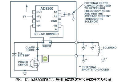
Figure 4. ECU with AD8200, low-side solenoid and high-side switch and detection. The AD8200 operates from a single +5 V supply. The input common-mode range is from -2 V to +24 V, which can reach +44 under no-load conditions.
V. If a higher common mode range is required, it is recommended to use other members of the AD8200 family - for example, the AD8205 with a CMV range of -2 V to +65
V, gain is 50; or AD8206, which has a CMV range of -2 V to +65 V and a gain of 20 (same as the gain of the AD8200). 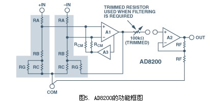
μV/°C and 10 ppm/°C. The device has a CMR minimum of 80 dB over the frequency range from DC to 10 kHz.
In addition to the SOIC package, the AD8200 is available in die (die) form. Both packages meet specified specifications over a wide temperature range, making the AD8200 ideal for a wide range of automotive and industrial platforms. SOIC package in -40
The specified technical specifications are achieved within the temperature range of °C to +125 °C. The die package meets the specified specifications within the temperature range of -40 °C to +150 °C.
The AD8200 can be connected to a 100 kΩ resistor at the output of the preamplifier. It can be used to form a low-pass filter with an external capacitor. It can also be used with an external resistor to set a preset gain other than 20.
Appendix Mechanical Transmission Control Early methods of controlling transmission shift points involve complex, speed-dependent hydraulic circuits. Shifting is achieved by varying the pressure of the liquid in a complex valve body. The hydraulic pressure is regulated by a regulator connected to the output shaft. The centrifugal force drives the regulator to drain the transmission oil and increase the pressure in the valve body. Methods adapted to changing driving conditions typically involve forcing the transmission to downshift or loading mechanical actuators at large accelerations.