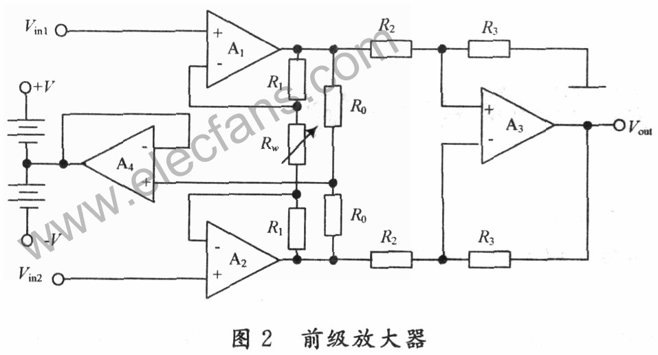
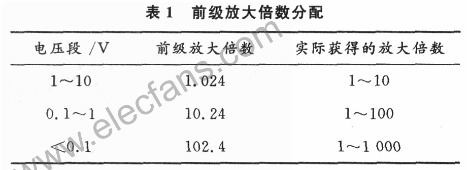
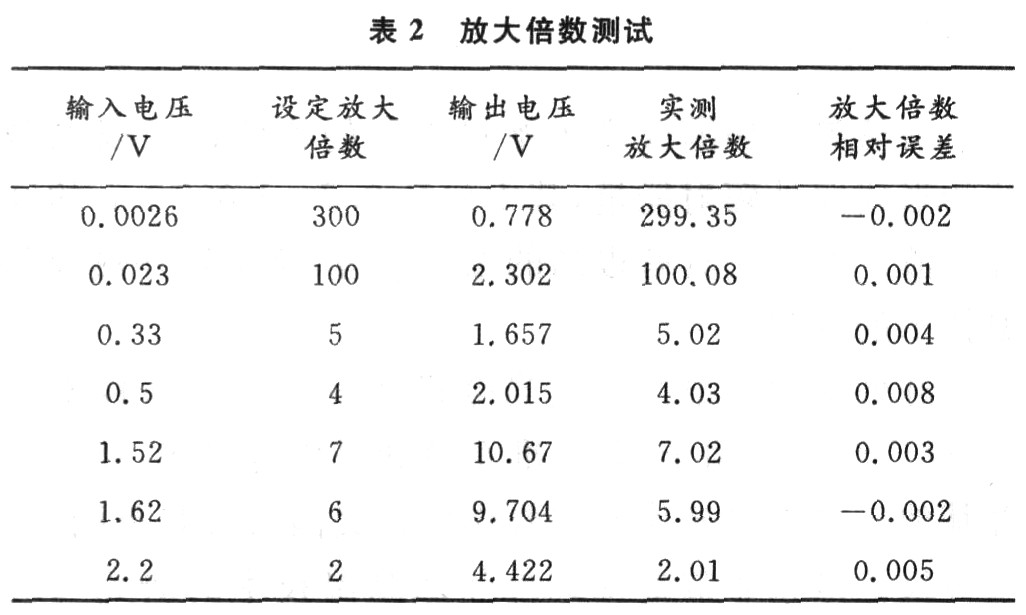
The measurement amplifier is also called an instrumentation amplifier or a data amplifier. It is a high-precision amplifier that can be used to amplify weak difference signals. It has a wide range of uses in measurement control and other fields. Generally, measurement amplifiers are mostly implemented with dedicated integrated modules. Although they have high performance indicators, it is not easy to realize gain presetting and digital control, and the price is higher. To this end, combined with the actual application, using high-gain op amps, a measurement amplifier with high common-mode rejection ratio and high-gain numerical control displayable is designed. The performance index of the measurement amplifier is improved, and the step adjustment of the amplifier gain in a larger range is realized. l Scheme design The measurement amplifier with a fixed magnification will inevitably have a great influence on the dynamic performance of the overall amplifier, so this design is mainly composed of three module circuits: the pre-stage high common mode rejection ratio measurement amplifier, the AD7533 attenuator and the single-chip keyboard display processing module . In the pre-stage high common mode rejection ratio amplifier, the output common mode voltage is fed back to the common terminal of the positive and negative power supplies to improve the common mode rejection ratio. The attenuator implements digital programming of the attenuation rate. The one-chip computer keyboard display processing module controls the 8279 in real time and digitally controls the AD7533. The overall system block diagram is shown in Figure 1. It can be analyzed from the overall system block diagram that the system magnifies the input signal as: Among them, Ac is the amplification factor of the preamplifier, and ADAC is the attenuation rate of the attenuator. 1.1 Pre-amplifier The instrumentation amplifier is used here to form a high common-mode rejection ratio measurement amplifier. As shown in Figure 2, the op amp A4 realizes the output common mode voltage feedback to the power supply common terminal, so that the op amp power supply voltage floats with the common mode input voltage, so that all levels The bias voltage tracks the common-mode input voltage, so that the common-mode signal at all levels is greatly weakened, and the error voltage generated by the common-mode input voltage at the output of the amplifier is greatly reduced, improving the amplifier's common-mode rejection ratio. In the figure, Rw is composed of three parallel fixed resistance paths, and the three resistance paths are realized by three relays controlled by a single-chip microcomputer. It is easy to analyze and find that the magnification of this amplifier is: Therefore, change the Rw to obtain the preamp voltage magnification of 3 control levels, and control the signals of 3 different voltage segments of 1 to 10 V, 0.1 to 1 V and less than 0.1 V, respectively, through the way of relay switching Different magnifications are achieved, as shown in Table 1. 1.2 SCM and attenuator The one-chip computer part realizes the overall control and display, which is composed of 51 one-chip computer and 8279 keyboard display chip main body. The set number can be realized by 0-9 numeric keys and control keys such as addition, subtraction and preset number. Any input signal is multiplied by 10 times by the post-stage programmable attenuator on the basis of the previous stage amplification to obtain the final voltage amplification factor. The schematic diagram of single chip microcomputer and attenuator is shown in Figure 3. The appropriate selection of the preamplifier magnification under the control of the single-chip algorithm makes the principle of the relay action: select the smallest preamplifier and the smallest post-decay rate, which is caused by the preamplifier attenuator The error is as small as possible. The variable gain attenuator AD7533 is also controlled by the single-chip microcomputer, and different output and input voltage ratios can be obtained by inputting different 10-bit digital quantities. Adjust the corresponding attenuation rate to get the corresponding magnification. With the 10-bit AD7533, each time the digital quantity changes by 1 bit, the attenuation will change by 1/1 024, achieving a 1 000-fold voltage amplification with a step size of 1. For example, when you want to get the voltage magnification of 205, just set the AD7533 OCDH (205D), and select the previous stage magnification is 102.4, so you can get: 102.4 × 10 × 205/1 024 = 205 magnification; when you want to When the voltage magnification of 60 is obtained, as long as 600/1 024 is attenuated, and the previous stage magnification is selected as 10.24, then you get: 10.24 × 10 × 600/1 024 = 60 magnification; when you want to get a voltage of 6 In the case of magnification, as long as 600/1 024 is attenuated, and the previous stage magnification is selected as 1.024, this will result in: 1.024 × 10 × 600/1 024 = 6 magnification. 2 Test results According to the above ideas, the magnification test was carried out on the actually produced measuring amplifier. Input the corresponding DC signal, the result is shown in Table 2. 3 Conclusion It can be seen from the test results that the measurement amplifier has a large differential mode voltage amplification factor, can preset the amplification factor, and realize the display, which is intuitive and convenient. It can meet the requirements of small signal measurement with high accuracy in the range of 10 V. The first-level and second-level amplification can be reasonably distributed according to the preset voltage amplification factor, and the preset function of 1 to 1 000 amplification factor in steps of 1 is realized. At the same time, various improvements are adopted to increase the common Mode rejection ratio. H2R Bone Conduction Helmet Speaker H2R Bone Conduction Helmet Speaker,Waterproof Bluetooth Speaker,Waterproof Helmet Headphone,Bone Conduction Speaker Shenzhen Lonfine Innovation Technology Co., Ltd , https://www.lonfinesmart.com
![]()
![]()


