Insulated gate two-stage transistor IGBT is a device composed of two-stage transistor and MOSFET. It not only has fast switching characteristics of MOSFET gate voltage control, but also has two-stage transistor high-current processing capability and low saturation voltage drop. specialty. Compared with the IGBT module, the IPM module has the following characteristics: built-in drive circuit, overcurrent protection, short circuit protection, control power supply undervoltage protection, overheat protection and external output alarm. This article uses the IPM module PM25RLA120 of Mitsubishi Corporation of Japan and the motor control chip UC1637 of American TI Corporation for electric servo control.
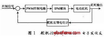
1 design principle The principle block diagram of the servo control is shown in Figure 1.

The servo is a position servo driver. Its working principle is: the control signal is compared with the servo position feedback signal to obtain a DC bias voltage. The bias voltage enters the signal modulation chip to generate a comparison level. After the PWM control chip UC1637 , Output a PWM signal with a certain duty ratio, used to drive the IGBT on and off in the IPM circuit, so as to realize the position control of the electric servo.
2 Servo control system circuit
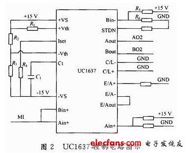
2.1 The control circuit with UC1637 as the core UC1637 is a chip designed by TI for DC motor control. This chip is used to replace the usual drive circuit, and contains a triangle wave generator, error amplifier, pulse width modulator, undervoltage protection The overcurrent protection circuit improves the integration of the motor control circuit and the reliability of the system. The steering gear control circuit receives the steering signal sent by the control computer, compares it with the steering gear feedback signal, corrects and amplifies the signal, and compares the signal with the triangle wave signal of a certain frequency amplitude to input UC1637, generates an analog error voltage signal in the chip Two PWM signals with different polarities can achieve the purpose of controlling the steering gear to play different rudder angles. The UC1637 control circuit is shown in Figure 2. MC2 is the triangle wave output signal, M12 is the UC1637 input control signal, A02 and B02 are the output control signals. After the two control signals are photoelectrically isolated, they control the on and off of different circuits of the IPM module to control the servo jobs.

ShenZhen Antenk Electronics Co,Ltd , https://www.antenkconn.com