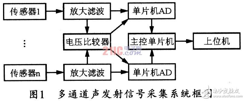
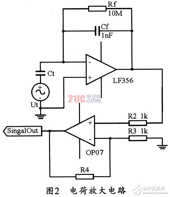
As a new dynamic monitoring technology, acoustic emission technology plays an important role in nondestructive testing technology. Non-destructive testing technology is a more common and effective method in fault diagnosis. Therefore, acoustic emission technology has broad application prospects in on-line detection of fault diagnosis. In particular, it is a large pressure vessel that is performing production tasks. Due to the need for long-term continuous non-stop production work, it is easy to cause fatigue damage of the pressure vessel, posing a serious threat to safety production. Acoustic emission detection can dynamically monitor large pressure vessels or tanks without interrupting production, and can quickly capture the location of defects, thus effectively avoiding major accidents. AcousTIc Emission technology is a non-destructive diagnostic tool that can be used to evaluate material or component damage. The so-called acoustic emission refers to a phenomenon in which a material spontaneously releases energy and generates a transient elastic wave under the action of an external force or an internal force. The elastic wave released by the material reflects some physical properties during the material destruction process, and the piezoelectric ceramic probe coupled to the surface of the material can convert the elastic wave generated by the acoustic emission source into an electrical signal, and then apply the electronic device. These electrical signals are amplified, sampled, and the collected data is transmitted to the host computer for storage and analysis. The elastic wave generated by the acoustic emission signal generated inside the material is subjected to the combination of reflection, diffraction and waveform conversion during the propagation process, thereby causing the attenuation of the elastic wave energy, so that the intensity of the acoustic emission signal is based on the sensor. The position is weakened by an increase in the distance from the acoustic emission source. Therefore, when the material deformation or crack formation point propagates to the sensor receiving point, the detected acoustic emission signal becomes very weak. The most important of the acoustic emission detection techniques is the positioning of the acoustic emission source, and the method and method of positioning the acoustic emission source is determined by the number of channels of the acoustic emission signal acquisition system. One-dimensional line positioning requires two acoustic emission signal channels, while two-dimensional planar positioning requires at least three acoustic emission signal channels. Therefore, the four-channel acoustic emission signal acquisition is the most widely used acoustic emission signal acquisition system. On this basis, it can be expanded to more channels of acoustic emission signal acquisition system. 2.1 The composition of the acoustic emission signal acquisition system The acoustic emission data acquisition system is mainly composed of sensors, preamplifiers, data acquisition, data communication, signal processing and other modules. Multichannel acoustic emission signal acquisition systems typically consist of four separate signal acquisition channels. This article will discuss the design of four independent signal acquisition systems in detail. Figure 1 shows a block diagram of a multi-channel acoustic emission signal acquisition system. 2.2 Acoustic emission signal amplification filter circuit Since the acoustic emission signal is very weak, it is necessary to select an amplifier with a high input impedance; and the charge amplifier has a high input impedance and good linearity. Moreover, because the acoustic emission probe is a piezoelectric ceramic, it has capacitive characteristics. Therefore, selecting an ordinary amplifier will cause the static charge during operation to be poured on the sensor plate, so that the sensor cannot output the detected signal normally. Therefore, in the present system, the first stage amplifying circuit selects the charge amplifier LF356, and FIG. 2 shows the charge amplifying circuit of the system. In the charge amplifier circuit, the resistance of the resistor and the capacitance of the capacitor must be selected to meet the signal frequency requirements of the sensor output: This design uses two-stage amplification, and the amplification factor A of the first-stage charge amplifier is designed to be 20, namely: Where: Ct is the equivalent capacitance of the transducer. The value of the feedback capacitor Cf is 1 nF, and the equivalent capacitance of the transducer is 20 nF. Thus, the Cf is 1 nF, and the resistance of Rf is 10. MΩ, then, bring the resistor and capacitor into the relationship: The frequency of the transducer output signal is greater than 60 Hz, ie: f "fx", which is greater than the cutoff frequency of the charge amplifier to meet the design requirements. Surface Mount Box,blank surface mount box,electrical mounting box,surface mount electrical box NINGBO UONICORE ELECTRONICS CO., LTD , https://www.uonicore.com


