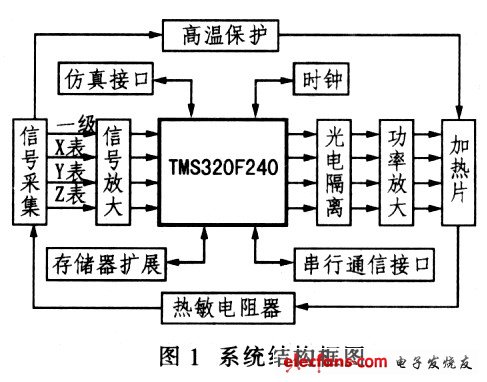
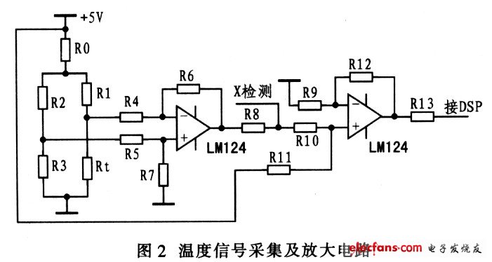
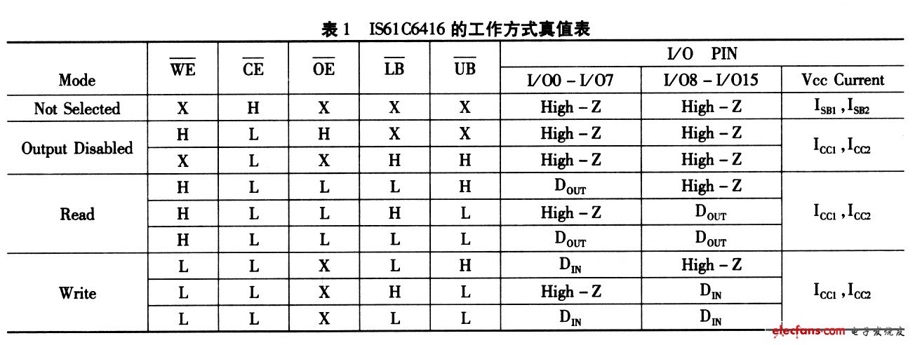
1 Introduction In recent years, digital signal processors (DSPs) have been rapidly developed and cost-effective, and are widely used in various fields, such as communication, voice processing, image processing, pattern recognition, and industrial control, and are increasingly showing great advantages. . The digital signal processor utilizes a special or general-purpose digital signal processing circuit to process the signal by digital calculation. It has the characteristics of fast processing speed, flexibility, accuracy, strong anti-interference ability, small size and high reliability. Fast, accurate, real-time processing and control requirements for signals. In this paper, the T1MS320F240 DSP is used as the core, and the high precision inertial navigation accelerometer temperature control system is designed. 2 Basic features of the TMS320F240 series The TMS320F240 combines the high-speed computing power and high-efficiency control of the DSP. Its main features are as follows: (1) The core CPU includes a 32-bit central arithmetic logic unit (CALU), a 32-bit accumulator, 16-bit & TImes, a 16-bit parallel multiplier, three scaling shift registers, and eight 16-bit auxiliary registers. The instruction cycle is 50 ns (20 MI/s), most instructions are single-cycle instructions; (2) On-chip with 544 Bxl6 data/program RAM and 16 KBx16 bit mask ROM or Flash EEPRClM, external memory interface with 16-bit address bus and 16-bit data bus, 224 KBx16-bit maximum addressable register space: (3) Dual 10-bit A/D converter can realize simultaneous sampling of two-way signals, and the conversion time can be programmed according to needs. The shortest conversion time is 6.1 IJ, s; (4) Six external interrupts, including power-drive protection interrupt, reset, non-maskable interrupt NMI, and three maskable interrupts. 3 temperature control system hardware design The DSP-based temperature controller simplifies the hardware design of the circuit by utilizing the powerful high-speed computing power of DSP and its rich control peripheral components and circuits integrated on-chip. It can implement various control algorithms and control strategies through asynchronous The serial communication interface reads the data that the user needs, and is convenient for the user to analyze the experimental results. In addition, it also has high temperature hardware protection from the DSP. It can eliminate the system over-temperature danger caused by the unexpected loss of control of the DSP system, and improve the reliability and safety of the operation of the temperature control system. The system structure is shown in Figure 1. 3.1 Signal acquisition and amplification circuit Signal acquisition circuit is an important part of temperature control system. Its accuracy in temperature measurement directly affects the accuracy of the entire temperature control system. Therefore, the system uses a stable performance PT1000 platinum thermal resistance sensor as a sensitive component for measuring temperature signals. The resistance value changes with temperature: the resistance value is 1 000 Ω at 0 ° C, and the temperature coefficient is 3.84 Ω ° C. Linearity is less than 0.5%. The signal acquisition circuit uses a symmetrical differential bridge to measure the temperature signal, and the platinum thermal resistor Rt and the precision resistors R1, R2 and R3 form a measurement bridge. X detection is the input signal of the hardware protection circuit, and the temperature signal acquisition and amplification circuit is shown in Figure 2. In order to improve the acquisition accuracy of the system, the bridge is powered by AD586, a high-precision reference source from Analog Devices, Inc., and a current limiting resistor RO is added in front of its bridge to make the current flowing through the platinum RTD less than 10 mA. In order to minimize the effect of the self-heating effect of the platinum thermal resistor during operation on temperature acquisition. When the temperature changes, the resistance of the platinum thermal resistor Rt also changes, and the bridge output signal is amplified by the operational amplifier and subjected to corresponding bias processing. The voltage is made to meet the voltage input range of the V on-chip AID converter from 0 V to 5 V for AID conversion. 3.2 External Memory Expansion In the temperature control process, a large amount of data needs to be collected and processed. The inherent on-chip data memory space of the TMS320F240 is obviously not enough. and. If there is external memory when debugging the system, simply download the program to the external memory through the emulation interface without burning it into the on-chip Rash. This brings convenience to program debugging. Therefore, the IS61C6416 static memory manufactured by ISSI is used to expand the external memory. The IS61C6416 is a 64 Kxl6bit static memory fabricated in a CMOS process. Available in a 44-pin SMD package with 5.0 V supply. The input and output levels are compatible with TTL levels and feature high speed read and write access times and low power operation. Table 1 shows the working mode truth table of IS61C6416. The interface circuit between IS61C6416 and TMS320F240 is very simple. Its 16 data lines and 16 address lines can be directly connected to the TMS320F240. As can be seen from Table 1, the working mode of IS61C6416 is controlled by five control signal lines, wherein the enable pin and the read/write select pin are connected to the DSP to control its read and write operations. Since the TMS320F240 series DSP is a 16-bit microprocessor, its Data reading and writing are not performed separately, so the high byte and low byte enable pins are directly grounded. Concentric Cable-Ks04-1022,Al Concentric Cable,Copper Concentric Cable,Concentric Neutral Cable HENAN QIFAN ELECTRIC CO., LTD. , https://www.hnqifancable.com

