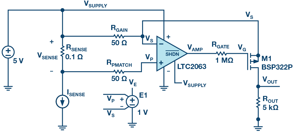
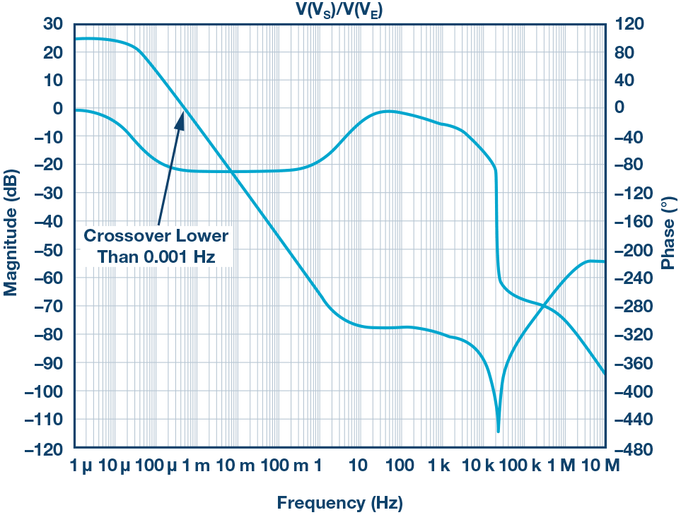
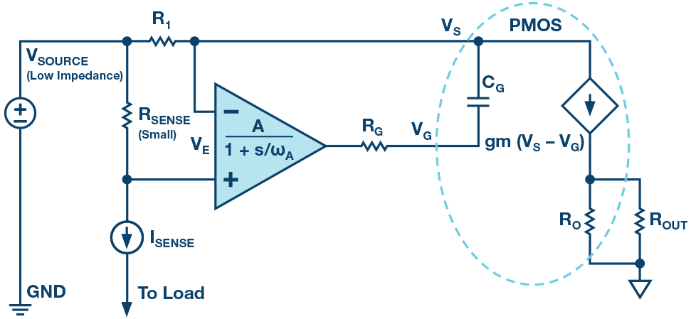
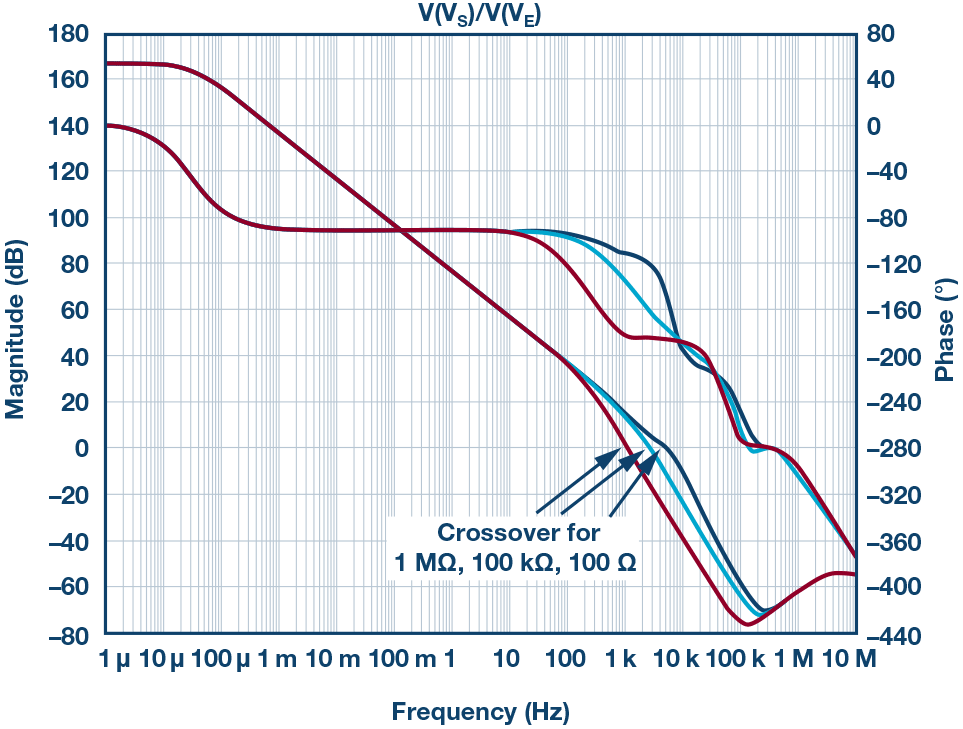
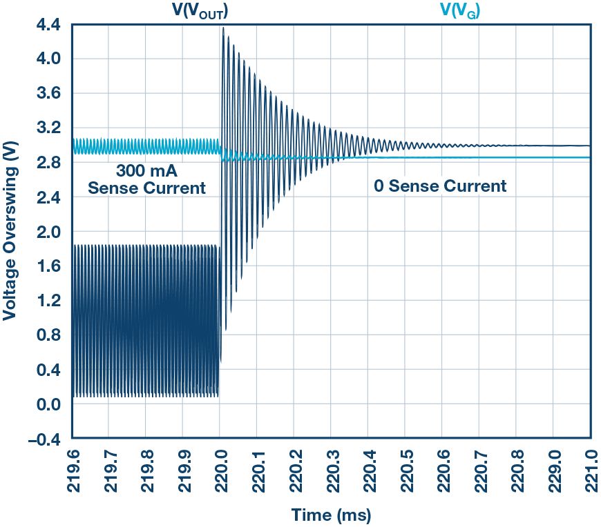
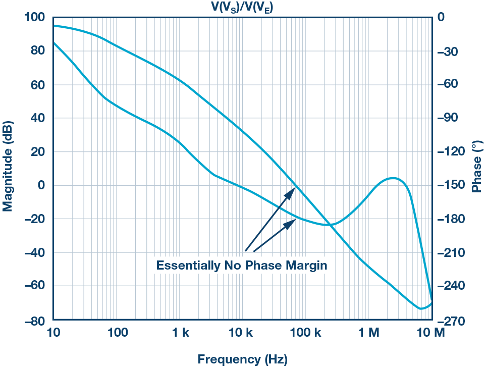
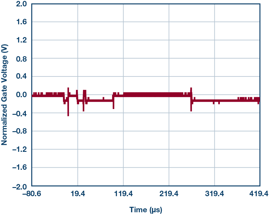
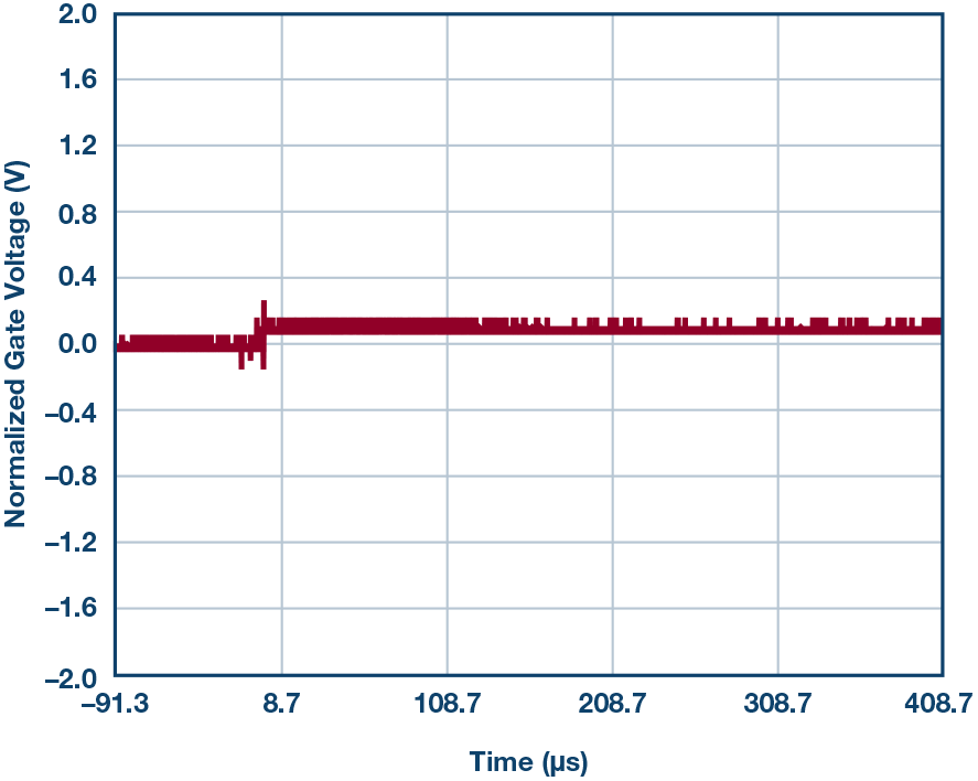
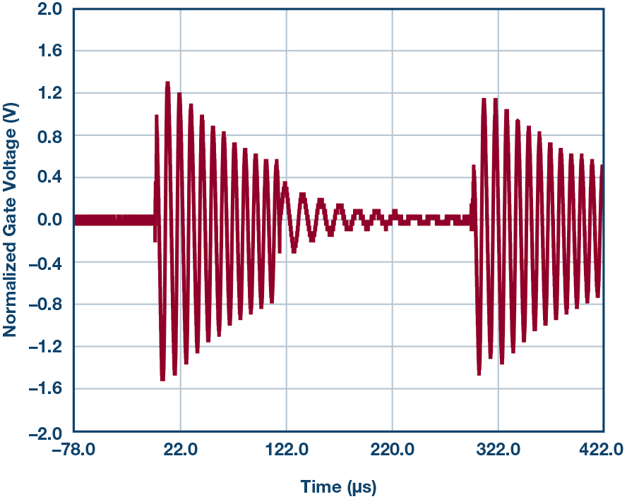
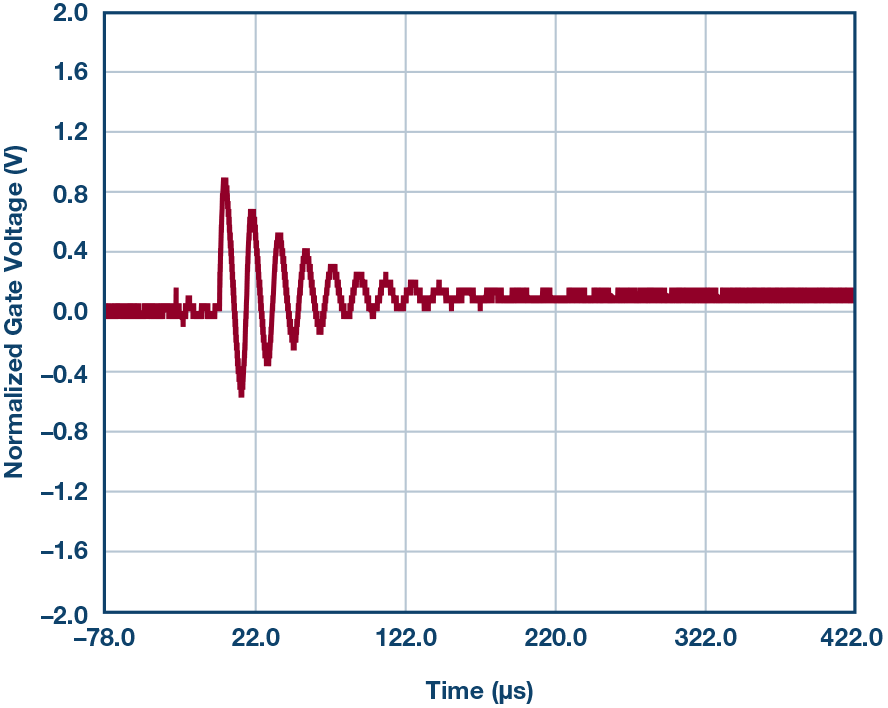
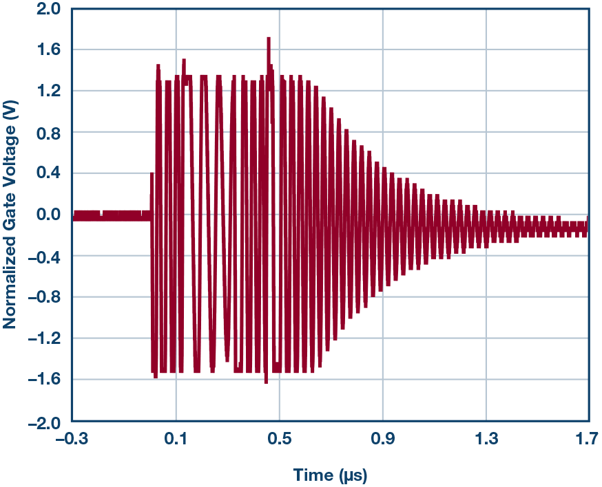
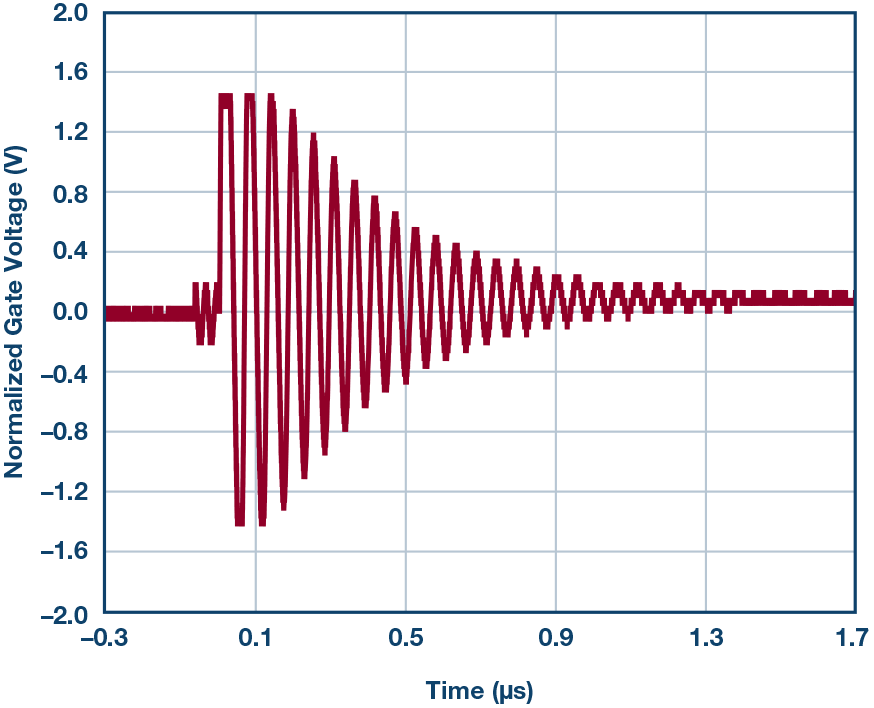
Just ask any experienced electrical engineer - like Professor Gureux in our story - what to put in front of the MOSFET gate, and you'll probably hear "a resistance of about 100 ohms." Although we answered the question Very sure, but people still ask why and want to know the specific role and resistance value. In order to satisfy people's curiosity, we will discuss these issues through an example. The young application engineer, Neubean, wanted to prove through experiments that in order to obtain stability, it is not really necessary to place a 100 Ω resistor in front of the MOSFET gate. Gureux, an application engineer with 30 years of experience, oversaw his experiment and provided expert guidance throughout the process. High-end current detection Figure 1. High-side current detection. The circuit in Figure 1 shows a typical high-side current sense example. Negative feedback attempts to force voltage VSENSE on gain resistor RGAIN. Current through RGAIN flows through the P-channel MOSFET (PMOS) into resistor ROUT, which forms a ground-referenced output voltage. The total gain is The optional capacitor COUT on resistor ROUT acts to filter the output voltage. Even if the drain current of the PMOS quickly follows the detected current, the output voltage exhibits a single-pole exponential trajectory. The resistor RGATE in the schematic separates the amplifier from the PMOS gate. What is the value? The experienced Gureux may say: "Of course it's 100 ohms!" Try multiple Ω values We discovered that our friend Neubean, who is also a student of Gureux, is seriously thinking about this gate resistance. Neubean is thinking that if there is enough capacitance between the gate and source, or the gate resistance is large enough, it should cause stability problems. Once it is determined that RGATE and CGATE will have an adverse effect on each other, it is possible to uncover 100 Ω or any gate resistance value as the reason for a reasonable answer. Figure 2. High-side current sensing simulation. Figure 2 shows an LTspice simulation example for highlighting circuit behavior. Neubean demonstrates stability through simulations. He believes stability issues will occur with increasing RGATE. After all, the poles from RGATE and CGATE should erode the phase margin associated with open loop. However, what surprises Neubean is that in the time domain response, all RGATE values ​​did not present any problems. As a result, the circuit is not simple Figure 3. Frequency response from error voltage to source voltage. In studying the frequency response, Neubean realized that it was necessary to specify what the open-loop response was. If combined with unit negative feedback, the forward path that constitutes the loop starts from the difference and ends at the negative input of the result. Neubean then simulates VS/(VP-VS) or VS/VE and plots the result. Figure 3 shows the frequency domain plot for this open loop response. In the Bode plot of Figure 3, the DC gain is small, and no phase margin problem is found at the crossover. In fact, from a whole point of view, this picture shows very strange because the crossover frequency is less than 0.001 Hz. Figure 4. Block diagram of the high-side detection circuit. The result of decomposing the circuit into a control system is shown in Figure 4. Like almost any voltage feedback operational amplifier, the LTC2063 features high DC gain and single-pole response. The op amp amplifies the error signal, drives the PMOS gate, and passes the signal through the RGATE-CGATE filter. The CGATE and PMOS sources are connected together to the –IN input of the op amp. RGAIN is connected from this node to a low impedance source. Even in Figure 4, it may seem that the RGATE-CGATE filter should cause stability problems, especially if RGATE is much larger than RGAIN. After all, the CGATE voltage, which directly affects the system RGAIN current, lags behind the output of the op amp. For why RGATE and CGATE do not cause instability, Neubean provides an explanation: “The gate source is a fixed voltage, so the RGATE – CGATE circuit is irrelevant here. You just need to adjust the gate and source as follows: Yes, this is a source follower." Gureux, a more experienced colleague, said: “In fact, this is not the case. This is only the case when PMOS is working as a gain module in the circuit.†Inspired by this, Neubean thought about the mathematics problem - if it can directly simulate the response of the PMOS source to the PMOS gate, what would happen? In other words, what is V(VS)/V(VG)? Neubean quickly ran to the whiteboard and wrote the following equation. among them, The op amp gain is A and the op amp pole is ωA. Neubean immediately discovered the important item gm. What is gm? For a MOSFET, Looking at the circuit in Figure 1, Neubean's heart shines. When the current through RSENSE is zero, the current through the PMOS should be zero. When the current is zero, gm is zero because the PMOS is actually off, unused, unbiased, and gainless. When gm = 0, VS/VE is 0, frequency is 0 Hz, VS/VG is 0, frequency is 0 Hz, so there is no gain at all, and the graph in Figure 3 may be valid. Trying to find instability with LTC2063 With this inspiration, Neubean quickly tried some simulations with non-zero ISENSE. Figure 5. Frequency response from error voltage to source voltage for non-zero sense current conditions. Figure 5 shows the response gain/phase diagram from VE to VS for the condition. The line spans 0dB up to 0dB and looks much more normal. Figure 5 should show that at approximately 2 kHz, there is a large amount of PM at 100 Ω, less PM at 100 kΩ, and even less at 1 MΩ, but it does not destabilize. Neubean came to the lab and used a high-end detection circuit LTC2063 to get a sense current. He inserts a high RGATE value, first 100 kΩ, then 1 MΩ, hoping to see unstable behavior, or at least some kind of ringing. Unfortunately, he did not see it. He tries to increase the drain current in the MOSFET by first increasing the ISENSE and then using the smaller RGAIN resistor value. The result still failed to make the circuit unstable. He returned to the simulation and tried to measure the phase margin with non-zero ISENSE. Even under simulation conditions, it is difficult and even impossible to find instability problems or low phase margin problems. Neubean finds Gureux and asks why he did not make the circuit unstable. Gureux suggested that he study the specific figures. Neubean has become accustomed to Gureux's profound knowledge, so he studied the actual poles formed by RGATE and the total capacitance of the grid. At 100 Ω and 250 pF, the pole is 6.4 MHz; at 100 kΩ, the pole is 6.4 kHz; at 1 MΩ, the pole is 640 Hz. The LTC2063 has a gain bandwidth product (GBP) of 20 kHz. When the LTC2063 has gain, the closed-loop crossover frequency can easily fall below any effect of the RGATE-CGATE pole. Yes, instability may occur Realizing that the dynamic range of the op amp needs to extend beyond the RGATE-CGATE pole, Neubean opted for a higher gain bandwidth product op amp. The LTC6255 5 V op amp can be added directly to the circuit and has a high gain bandwidth product of 6.5 MHz. Neubean eagerly simulated with current, LTC6255, 100 kΩ gate resistance, and 300 mA sense current. Then, Neubean added RGATE to the simulation. When RGATE is large enough, an extra pole may make the circuit unstable. Figure 6. Time domain chart with ringing. Figure 7. Normal Bode plot after increasing current (VE to VS) with poor phase margin performance. Figures 6 and 7 show simulation results at high RGATE values. When the detection current remains unchanged at 300 mA, the simulation will be unstable. Experimental results In order to understand whether the current will behave abnormally when detecting non-zero currents, Neubean tested the LTC6255 with different stepped load currents and three different RGATE values. In the event that the momentary switch cuts in more parallel load resistors, ISENSE goes from a base of 60 mA to a high value of 220 mA. There is no zero ISENSE measurement here because we have shown that the MOSFET gain in that case is too low. In fact, Figure 8 finally shows that when using 100 kΩ and 1 MΩ resistors, stability does suffer. Since the output voltage is strictly filtered, the gate voltage becomes a ring detector. Ringing indicates poor or negative phase margins, and the ringing frequency indicates the crossover frequency. Figure 8. RGATE = 100 Ω, current from low to high transients. Figure 9. RGATE = 100 Ω, current from high to low transients. Figure 10. RGATE = 100 kΩ, current from low to high transients. Figure 11. RGATE = 100 kΩ, current from high to low transients. Figure 12. RGATE = 1 MΩ, current from low to high transients. Figure 13. RGATE = 1 MΩ, current from high to low transients. Brainstorming time Neubean realized that although many high-end integrated current-sensing circuits were seen, unfortunately, engineers were simply unable to determine the gate resistance because these were integrated in the device. Specific examples are the AD8212, LTC6101, LTC6102, and LTC6104 high-voltage, high-side current-sensing devices. In fact, the AD8212 uses PNP transistors instead of PMOS FETs. He told Gureux: "It really doesn't matter because modern devices have solved this problem." As if waiting for this moment, the professor almost interrupted the words of Neubean and said, "We assume that you want to combine very low supply currents with zero-drift input imbalances, such as battery-powered instruments installed in remote locations. You may use Use the LTC2063 or LTC2066 as the main amplifier, or you need to measure the low-level current through the 470 Ω shunt resistor and try to minimize the noise as much as possible.In that case, you may need to use the ADA4528, which supports rail-to-rail input In these cases, you need to deal with the MOSFET driver circuit." and so… Obviously, as long as the gate resistance is too large, it is possible to make the high-side current detection circuit unstable. Neubean talks to his helpful teacher Gureux about his findings. Gureux said that in fact, RGATE may indeed make the circuit unstable, but at first it could not find this behavior because the problem was incorrectly mentioned. Need to have gain, in the current circuit, the measured signal needs to be non-zero. Gureux replied: "Sure, when the poles erode the phase margin at the crossover, ringing will occur. However, it's ridiculous to increase the 1 MΩ gate resistance, and even 100 kΩ is crazy. It is a good practice to limit the output current of the op amp and prevent it from shifting the gate capacitance from one supply rail to another. Neubean agrees. "So, what kind of resistance value do I need to use?" Gureux replied with confidence: "100 Ω."
Shenzhen WeiKa Technology Co.,Ltd. is a professional e-cigarette manufacturer and enterprise integrating R&D, design, production and sales and service of the electronic cigarette atomizer products, established in 2020.
We are actively developing and producing all kinds of reliable and unique atomizer products. We centre on research, developing, high quality and safety, and focus on better vaping experience in all aspects to our customers. We have advanced production equipment and strict production control system, each process has strict management, from production to delivery have been strictly tested to ensure the classic quality. Zgarvape for the future!
Aurora E-cigarette Cartridge is loved by the majority of consumers for its gorgeous and changeable colors, especially at night or in the dark. Fruits Flavors series, plant flavors series & special flavors series.Up to 16 different flavors for choices. A new design of gradient our disposable vape is impressive. Our vape pen and pods are matched with all the brands on the market. You can use other brand's vape pen with our vape pods. Aurora series Pods systems, the first choice for professional users!
16 Available Flavors (3Pods*2ml):
Amazing Cantaloupe / Coke on the Rocks / Ice Coconut / Ice Lolly / Iced Mung Bean / Longjing Tea / Mango Feast / Mountain Spring / Peach Tempting / Pineapple Juice / Refreshing Melon / Refreshing Mint / Rich Strawberry / Rose Litchi / The Ocean / Watermelon Juice
Aurora Pods 1.0,Pod System Vape,Pos Systems Touch Screen,Empty Disposable Vape Pod System,400Puffs Pod Vape System ZGAR INTERNATIONAL(HK)CO., LIMITED , https://www.oemvape-pen.com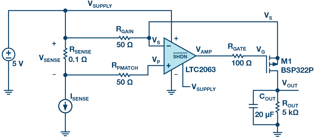



Aurora Disposable Vape Device Vaping Pod Systems


