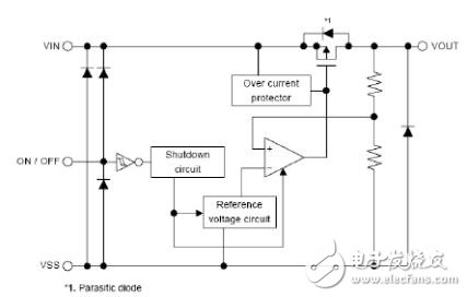
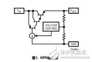
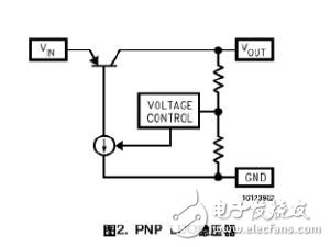
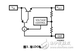
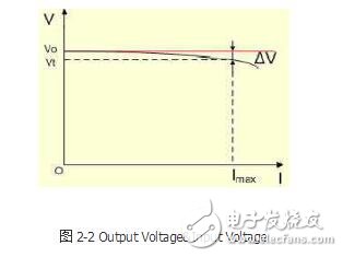
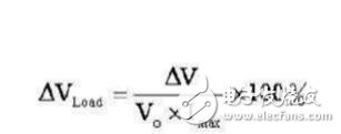
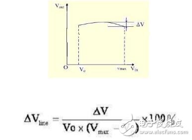
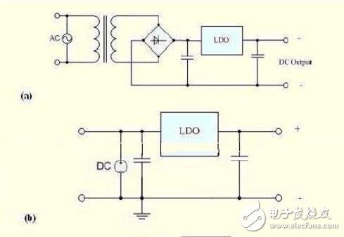
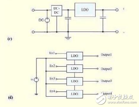
LDO is a linear regulator. A linear regulator uses a transistor or FET that operates in its linear region to subtract the excess voltage from the applied input voltage to produce a regulated output voltage. The so-called voltage drop voltage is the minimum value of the input voltage and output voltage difference required by the regulator to maintain the output voltage within 100mV of its rated value. LDO (low dropout) regulators with positive output voltage typically use power transistors (also known as transfer devices) as PNPs. This transistor allows saturation, so the regulator can have a very low voltage drop voltage, typically around 200mV; in contrast, a conventional linear regulator using an NPN composite power supply has a voltage drop of about 2V. The negative output LDO uses NPN as its transfer device and operates in a similar manner to the PNP device that is outputting the LDO. The updated development uses CMOS power transistors, which provide the lowest voltage drop voltage. With CMOS, the only voltage drop across the regulator is caused by the ON resistance of the load current of the power supply. If the load is small, this method produces a voltage drop of only a few tens of millivolts. The structure of the LDO low-dropout linear regulator mainly includes a start-up circuit, a constant current source bias unit, an enable circuit, an adjustment component, a reference source, an error amplifier, a feedback resistor network, and a protection circuit. The basic working principle is as follows: the system is powered on. If the enable pin is at a high level, the circuit starts to start, the constant current source circuit provides a bias to the entire circuit, the reference source voltage is quickly established, and the output continues to rise as the input rises. When the specified value is reached, the output feedback voltage obtained by the feedback network is also close to the reference voltage value. At this time, the error amplifier amplifies the small error signal between the output feedback voltage and the reference voltage, and then amplifies the output to the output through the adjustment tube. Forming negative feedback ensures that the output voltage is stable at the specified value. Similarly, if the input voltage changes or the output current changes, this closed loop will keep the output voltage constant, ie: Vout=(R1+R2)/R2 &TImes;Vref The actual low dropout linear regulator also has other functions such as load short circuit protection, over voltage shutdown, thermal shutdown, reverse connection protection and so on. According to the working state of the adjustment tube, we often divide the regulated power supply into two categories: linear regulated power supply and switching regulated power supply. In addition, there is a small power supply that uses a Zener. The linear regulated power supply mentioned here refers to the DC stabilized power supply in which the regulating tube operates in a linear state. In the switching power supply, it is different. The switch tube works in both on and off states. Briefly introduce the classification: NPN regulator: Internally use a PNP tube to control the Darlington adjustment tube. LDO regulator: The adjustment tube is a PNP tube. Squasi-LDO: The adjustment tube is controlled by a PNP tube. An NPN tube LDO (low drop output) low dropout linear regulator The LDO works by adjusting the Vsd voltage drop of the MOSFET through feedback to keep the output voltage constant. The output voltage ripple is small and the current is small. It is used for circuits with high voltage requirements such as RF modules or audio modules. The feature is low cost and low noise. The disadvantage is low efficiency, low output current, and can only be used in buck. It must be noted that negative feedback must be used in order to achieve a stable loop. Below is the basic schematic of the LDO S-1167 Series. The circuit is mainly composed of a series adjustment tube, a sampling resistor, and a comparison amplifier. The sampling voltage is applied to the non-inverting input terminal of the comparison amplifier, and compared with the reference voltage Uref applied to the inverting input terminal, the difference between the two is amplified by the amplifier A, and the voltage drop of the series adjustment tube is controlled to stabilize the output voltage. When the output voltage Uout decreases, the difference between the reference voltage and the sampling voltage increases, the drive current of the comparison amplifier output increases, and the series regulator tube voltage drop decreases, thereby increasing the output voltage. Conversely, if the output voltage Uout exceeds the desired set value, the pre-drive current of the comparator output is reduced, thereby reducing the output voltage. During the power supply process, the output voltage correction is continuously performed, and the adjustment time is limited only by the reaction speed of the comparison amplifier and the series regulator tube loop. Negative feedback in the loop always forces the comparator amplifier to regulate the voltage across the input to be equal. Another important indicator of the Zener diode is stability. In our design circuit, it is often seen that there will be large and small capacitors at its output. What is the function? The following is a detailed analysis of the feedback and loop of the Zener diode. stability. As mentioned earlier, the Zener tube: 1, NPN regulator tube For example: LM340 LM317 older 3-terminal regulator 2, LDO regulator tube Example: S-1167 Series 3. Quasi-LDO regulator The biggest difference between the regulators is the voltage drop and ground pin current. It is obvious that the NPN and quasi-LDO regulators are slightly more complicated on the adjustment tube, so the voltage drop is also larger. The Darling tube has a high gain, so it only needs a small current to drive. The same applies to the quasi-LDO, and the IGND is small. The amplification factor of the PNP tube is generally 15-20, and the IGND current of the LDO can reach 7% of the load current. The biggest benefit of NPN regulators is unconditional stability (most do not require external capacitors), and LDOs require capacitors at the output to reduce loop bandwidth and provide positive phase compensation. All regulators use a negative feedback loop to keep the output voltage stable. However, the feedback signal has a certain gain and phase change after passing through the loop. If the phase of the feedback signal changes by 180 degrees, the negative feedback will become positive feedback, causing the output to be unstable. Therefore, the feedback signal needs to have a phase margin of at least 20 degrees through the phase shift of the entire loop, so as to ensure the stability of the circuit. (The phase margin is defined as the difference between the total phase offset of the loop and -180 degrees). 1, the output voltage (Output Voltage) The output voltage is the most important parameter of the low-dropout linear regulator, and is the first parameter that electronics designers should consider when choosing a regulator. Low dropout linear regulators are available in fixed output voltages and adjustable output voltages. The fixed output voltage regulator is convenient to use, and since the output voltage is precisely adjusted by the manufacturer, the regulator has high precision. However, the set output voltage values ​​are common voltage values, and it is impossible to meet all application requirements, but the change of external component values ​​will affect the stability accuracy. 2, the maximum output current (Maximum Output Current) The power of the powered device is different, and the maximum current required by the regulator is also different. In general, the higher the output current, the higher the cost of the regulator. In order to reduce the cost, in a power supply system composed of a plurality of voltage regulators, an appropriate voltage regulator should be selected according to the current value required for each part. 3, input and output voltage difference (Dropout Voltage) The input-to-output voltage difference is the most important parameter for low dropout linear regulators. Under the condition that the output voltage is stable, the lower the voltage difference, the better the performance of the linear regulator. For example, a 5.0V low-dropout linear regulator can stabilize the output voltage at 5.0V by inputting 5.5V. 4. Ground current (Ground Pin Current) The grounding circuit IGND refers to the operating current of the regulator provided by the input power supply when the output current of the series regulating tube is zero. This current is sometimes referred to as quiescent current, but this convention is incorrect when using PNP transistors as series regulator tube components. Generally, the ideal low-dropout regulator has a small ground current. 5. Load Regulation Rate (Load RegulaTIon) The load regulation rate can be defined by Figure 2-1 and Equation 2-1. The smaller the load regulation of the LDO, the stronger the LDO's ability to suppress load interference. Where Vload - load regulation rate Imax - LDO maximum output current Vt—When the output current is Imax, the output voltage of the LDO—the output current is 0.1mA, the output voltage of the LDO V - the difference between the output voltages when the load current is 0.1 mA and Imax, respectively. 6. Linear Regulation (Line RegulaTIon) The linear adjustment rate can be defined by Figure 2-2 and Equation 2-2. The smaller the linear adjustment rate of the LDO, the smaller the influence of the input voltage change on the output voltage, and the better the performance of the LDO. Vline-LDO linear adjustment rate Vo-LDO nominal output voltage Vmax-LDO maximum input voltage V-LDO input Vo to Vmax' the difference between the maximum and minimum output voltages. 7. Power Supply Rejection Ratio (PSSR) The input source of the LDO often has many interfering signals present. The PSRR reflects the LDO's ability to suppress these interfering signals. A typical application of a low dropout linear regulator is shown in Figure 3-1. The circuit shown in Figure 3-1(a) is the most common AC/DC power supply. After the AC power supply voltage is passed through the transformer, it is converted into the required voltage, which is rectified to become a DC voltage. In this circuit, the function of the low dropout linear regulator is to stabilize the output voltage when the AC power supply voltage or load changes, suppress the ripple voltage, and eliminate the AC noise generated by the power supply. The operating voltages of various batteries vary within a certain range. In order to ensure a constant voltage output from the battery pack, a low-dropout linear regulator should normally be connected to the output of the battery pack, as shown in Figure 3-1(b). Low-dropout linear regulators have lower power, which extends battery life. At the same time, since the output voltage of the low-dropout linear regulator is close to the input voltage, the output voltage can be stabilized when the battery is nearly discharged. As is known, the efficiency of the switching power supply is very high, but the output ripple voltage is high, the noise is large, and the voltage regulation rate is also poor, especially when the analog circuit is powered, it will have a greater impact. Connect the low-dropout linear regulator to the output of the switching regulator, as shown in Figure 2-3(c), to achieve active filtering, and also greatly improve the regulation accuracy of the output voltage, while the power system The efficiency will not be significantly reduced. In some applications, such as radio communication equipment, which is usually powered by only one battery, each part of the circuit is often isolated from different voltages, so it must be powered by multiple regulators. In order to save the power of the common battery, it is generally desirable that the low dropout linear regulator operates in a sleep state when the device is not operating. To this end, linear regulators are required to have an enable control terminal. A power supply system with a single battery-powered multi-output and on-off control function is shown in Figure 3-1(d). Dongguan Guancheng Precision Plastic Manufacturing Co., Ltd. , https://www.dpowergo.com