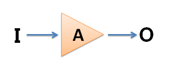
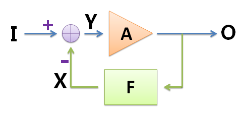
In the electronics profession, analog circuits are a very important lesson, and many people find it difficult. Here I will talk about my understanding of the analog circuit course, I hope to be helpful to everyone. Engineering Thoughts If you say test scores, my test scores are average, not high scores; but when it comes to the understanding and application of analog circuits, I have done some things with analog circuits and participated in some competitions. The analog circuit is an engineering course. The key to learning it is to master the engineering ideas, and it is best to use it in practice, not just to do the exam. What is engineering thinking? Baidu Encyclopedia's explanation is this: "Engineering is an application of science and mathematics. Through this application, the nature of matter and energy can be passed through various structures, machines, products, systems and processes. Time and fine manpower make things that are efficient, reliable, and useful to humans. So the concept of engineering has emerged, and it has evolved into an independent discipline and skill." For example, in analog circuits, there is a very Important engineering ideas - approximation. The basic concept of negative feedback is that some very powerful people have found a good way: negative feedback. What is negative feedback? “Feedback refers to returning the output of the system to the input and affecting the input, thus affecting the overall output of the system. The feedback can be divided into positive feedback and negative feedback. Negative feedback is to make the output play the opposite role to the input, so that the system The output tends to be stable." The above explanation is not easy to understand. I will give two examples. When playing the inverted pendulum, we support an inverted wooden stick by hand. When the wooden stick is tilted in a certain direction, we offset this change by moving the hand to the direction in which the stick is tilted, so that the stick can be in the hand. balance. When I was in high school, I often took monthly exams. I found that some students have such a habit: when a grade is poorly tested, they will start to study hard, and then the next grade will rise. When the exam is better, the next one will be The month will be lax, so the results will fall again, so it will be repeated. Both examples fully demonstrate that negative feedback can make the system more stable. Negative Feedback Amplifiers We ignore specific circuits and draw a simple block diagram to illustrate how the triode amplifier circuit uses negative feedback. The triangle below represents an amplifier composed of a triode with a magnification of A and an input of I, and the output is O=I∗A. Since the amplification factor A is unstable, the output waveform is distorted. Some devices have been added to the circuit as follows. The purple circle is the adder, combined with the purple "+" and "-" symbols, indicating that its output Y = (+I) + (−X) = I−X, which can be realized by using a resistor in the actual circuit; Block F is a feedback device that indicates that the signal is taken from output O and multiplied by F to obtain X, so X = O ∗ F, where F < 1 (this part can be implemented with a resistor in the actual circuit); The amplifier A is mainly composed of a triode, which satisfies O=A∗Y, and the amplification factor of A is unstable and is easily disturbed. The equations can be listed: Y=I−XO=Y∗AX=O∗F solves the magnification of the entire circuit: If the design circuit makes the magnification A very large, and F is not too small, the A∗F》"1 symbol """" means much larger than the approximate circuit, the above circuit magnification: Since the feedback device can be realized by a resistor, the resistance of the ordinary resistor is not easily disturbed by the outside, so the value of F is stable, and the amplification factor of the entire circuit is stable. We successfully solved the problem of the amplification stability of the triode through negative feedback. It can be seen that the feedback part and the amplifying part here constitute a ring shape, so the amplification factor of the whole circuit is called loop gain, or closed loop gain; and before the feedback is added, the amplification factor A of the circuit is called open loop gain. Because of the negative feedback, although the gain stability of the circuit is improved, there is also a price: since the AF"1 is then A""1/F, the open-loop gain is much larger than the closed-loop gain, that is, the amplifier gain is greatly reduced. But in general, for stability, this is worth it. Operational Amplifier In the above circuit, in order to actually manufacture an amplifier with a large open-loop gain A, it is often designed in a multi-stage triode amplification circuit in series. In the middle of the straight line, the normal amplification state, called the linear region, satisfies Uo=A∗(U+−U−). When the absolute value of the input is slightly larger, the output is limited by the power supply. To satisfy the above relationship, the value of Uo is usually slightly smaller than the power supply voltage range (note that the op amp can use dual power supplies, that is, the power supply voltage range can be between a negative value and a positive value), which is called a nonlinear region. The output of the rail-to-rail op amp can reach the power supply voltage, and you are interested in searching and learning online. Solar Inverter Kit,Wifi Module,Inverter Parallel Kit,Monitoring Card Shenzhen Unitronic Power System Co., Ltd , https://www.unitronicpower.com
In the middle school physics class, many of the circuits we learned are ideal circuits. The wire resistance is always 0, the efficiency of the transformer is 100%, the internal resistance of the ideal voltmeter is infinite, and the internal resistance of the ideal ammeter is 0. You can see that many times the calculations in analog circuits often omit one or two smaller items and use the equal sign instead of the equal sign.
Why use an approximation? To put it bluntly, human science's understanding of nature is not comprehensive enough to describe natural phenomena absolutely or accurately; or humans have limited understanding and accurate descriptions are too costly. By approximating means, not only has no obvious effect on solving the problem, but also greatly simplifies the steps, saving time and effort. Using this idea, human science has achieved many results and fully proved its reliability. The schematic model itself is a very complex subject, and the modular model is only the most basic one. The meaning of an analog circuit is an electronic circuit that processes an analog signal. Most of the signals in nature are analog signals, which have continuous amplitude values, such as the sound signal when speaking. The analog circuit can directly process such a signal (of course, it needs to be converted into an electrical signal first), for example, the power amplifier can amplify the sound signal, and the broadcast station can transmit the analog sound signal and the image signal. It can even be assumed that the basis of all circuits is analog circuits (even digital circuits, the underlying principle is based on analog circuits). Its importance is self-evident. Due to the rapid development of digital circuits and programmable devices, many superior features have been demonstrated. Many electronic devices are slowly digitized, but they are still inseparable from analog circuits. The most important devices in analog circuits today are non-semiconductor devices. The most basic and commonly used semiconductor devices are diodes, transistors, field effect transistors, and operational amplifiers.
Diodes have many functions, such as ordinary diodes for rectification, LEDs for indicators and illumination, Zener diodes for voltage regulation, and varactors for signal modulation. In the model electricity course, the part related to the diode is relatively simple, and many characteristics of the field effect tube are similar to the triode, so the triode or op amp is often used as the main body to explain. The basic function of the triode and amplifier triode is to amplify. Through this characteristic, the triode constitutes various circuits, which reflects many engineering ideas. The basic circuit of a triode is an amplifier. For example, a power amplifier is an amplifier, and the input sound is small, and the output sound is large. The ratio of the output of the amplifier to the input voltage (or current) is called the amplification factor, also known as the gain. For a voltage, if the time is plotted on the horizontal axis and the voltage is plotted on the vertical axis, this graph is the waveform of this voltage. If a amplifier with a magnification of 5 inputs a constant 1V voltage (the waveform is shown below), the output should always be 5V (the waveform is shown below), neither changing with time nor changing with temperature, output It is exactly the same shape as the input voltage. However, if the magnification is unstable and constantly changing, the originally input signal will be distorted (as shown in the right figure below), and the signal may be changed from a horizontal line to a curve. This waveform change is called distortion. 


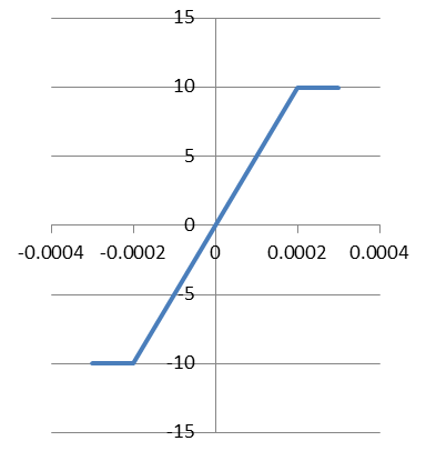
Since the demand for such high-gain amplifiers is very common, some people have historically made them into a finished circuit board module, which is very convenient when used as a component. This is the original operational amplifier, referred to as the op amp. The development of integrated circuits has made it possible to integrate a large number of transistor components on a small chip, so there is an integrated operational amplifier that is very commonly used today. The "Operational Amplifier" is named for its initial use in mathematical operations on analog computers. Although the digital computers that are widely used today no longer use the op amp for calculations, the name is retained. Today, the operation of the analog circuit plays a very important role, and has become one of the focuses of the model. The short-and-short-break characteristic of an op amp usually has two inputs U+ and U− and one output Uo. The Uo=A∗(U+−U−) op amp open-loop gain A is often as high as tens 10,000 to several million, but the output voltage of the op amp is limited by the power supply voltage and cannot exceed the power supply voltage. The input-output relationship of the op amp is then similar to the shape of the figure below. In the figure, the horizontal axis is (U+−U−) and the vertical axis is Uo. 
When the op amp is operating in the linear region, the value of Uo is very limited, but A is very large, so U+−U−=UoA≈0 is U+≈U−. At this time, the positive and negative input voltages of the op amp are almost equal, just like a short circuit. The same, called virtual short. Therefore, only when the op amp works in the zoom-in area will it have the characteristics of “virtual shortâ€, not the inherent properties of the op amp. On the other hand, due to the internal structural characteristics of the op amp, its input impedance is large. The input impedance can be simply understood as input impedance = input voltage / input current input impedance is large, which means that the op amp input requires only a small amount of current to work properly. Because of this, the op amp can be used for the detection of some weak currents, such as the brainwaves and myoelectric waves of the human body. The highest voltage value is only a few mV, and the current value is also very small. This feature of the op amp is called a virtual break, that is, the input is the same as the open circuit, and almost no current flows in. Unlike virtual shorts, virtual breaks are inherent properties of the op amp and do not change with the circuit.
The non-ideal characteristics of the op amp are made up of triodes. Obviously, like the triode, there are many undesirable characteristics. All of the above are the characteristics of an ideal op amp. The actual op amp, it will not fully meet the virtual short-short characteristics, the input requires current flow in normal operation, this current is called the input bias current. The same op amp also has non-ideal parameters such as input bias voltage, input offset voltage, and input offset current. These non-ideal characteristics, such as the input bias current, are small, but sometimes they have a large impact on the circuit, making the circuit inoperable. Therefore, there are some ways to reduce the impact of these factors. In practical applications, the non-ideal nature of the op amp is a very important issue. There are many ways to eliminate the non-ideal characteristics of an op amp, which will not be introduced here. The core of other content modeling courses is the triode and op amp. Around these devices, explain a variety of circuits, including: calculation and analysis of amplifier circuits, multi-stage amplifier circuits, frequency characteristics of amplifiers, feedback ideas; power amplifier circuits; comparators, oscillators, integrators, differentiators, waveform generation, etc. ; signal processing; filter; integrated power supply circuit. Comparison of Op amps and Transistors When actually designing a circuit, the op amp is used more than the triode. Because many of the characteristics of the op amp are better than the triode, the circuit design is simple, and the cost of the op amp is often not high.
Many times the same effect is achieved with a triode and an op amp, and the cost of using an op amp is even lower. Because op amps integrate a large number of transistors, the average manufacturing cost per transistor is very low. For example, a conventional audio preamplifier, a general-purpose op amp can be fixed, the cost may be 0.2 yuan, and the same effect can be achieved with a triode, which may require 10 or more triodes, the cost may be 0.5 yuan, and the design cost The labor cost is much higher than the op amp solution. Of course, the triode also has its advantages. In some very simple circuits, the stability of the magnification is not strictly required. One or two transistors can accomplish the task, and the triode is often used to save costs. In addition, under some extreme conditions, such as working in high frequency, high power environment (such as RF signal transmission circuit), the performance of well-designed triode circuit will be much better than the op amp, or the cost is much lower, and even some In this case, only the transistor can be used directly. In this case, a triode is needed to build the circuit.
Recommended bibliography on the study of analog circuits, I recommend a few books: one is Tsinghua University Tong Shibai, Hua Chengying teacher editor of the "simulated electronic technology foundation." This book is a relatively classic model teaching material, which is developed around the triode and explained in more detail. The other is "The Analog Electronic Circuit and Technology Foundation" edited by Xi Xiaosun Xiaozi. This textbook personally feels very good, and unlike most of the electro-mechanical textbooks, this book revolves around the op amp, introduces feedback and other ideas and various circuits, and then talks about the triode. The op amp is much easier to solve than the three-pole management, because the op amp integrates the complicated computational analysis into its interior, and we don't need to pay attention to its internal structure at first. This kind of energy can be completely placed on the understanding of various circuit principles. There is also an introductory book, "Electronic Design from scratch" published by Tsinghua University. This book is an introductory book for electronic design. It is not just analog circuits, but also digital circuits and microcontrollers. The introduction of the Ending Mode Electric Course ends here. But what I want to say is that analog circuits are a very complex subject, and the knowledge involved is much more than just those in the book. The book is generally introduced according to the working principle, which simplifies many problems that are difficult to understand but must be considered in practice, so the gap between the actual circuit and the book is very large. For example, a triangular wave generator built by an op amp in a mold book is used for practical circuits. However, the main principles of the actual circuit are consistent with the description in the book. Therefore, designing analog circuits often requires a lot of experience, and there are many things that are even difficult to explain and cannot be calculated. I hope this article can help students who are learning analog circuits.