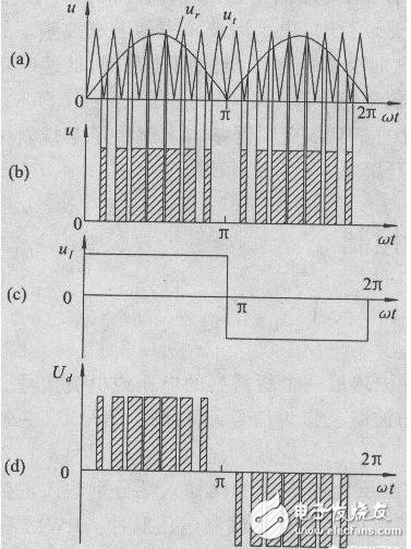
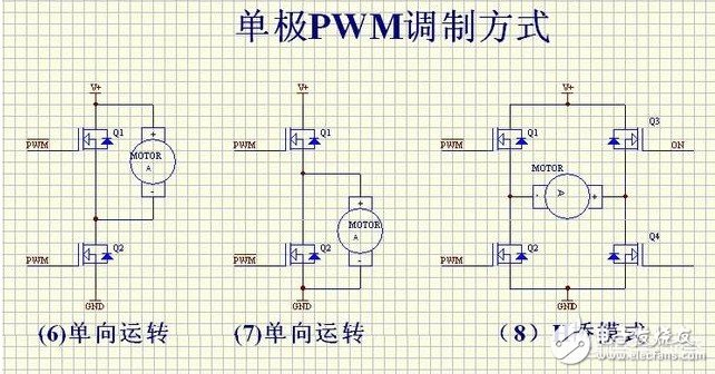
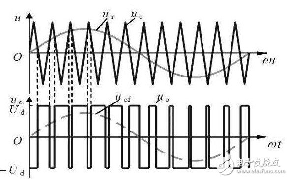
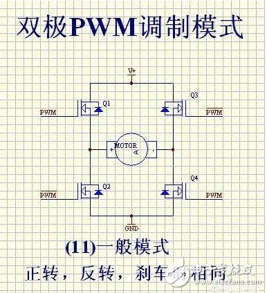
This article is mainly about the related introduction of unipolar and bipolar PWM modulation, and focuses on the detailed description of the difference between unipolar and bipolar PWM modulation. PWM (PulseWidthModulaTIon) control is a technique to modulate the width of the pulse. That is, by modulating the width of a series of pulses, the desired waveform can be obtained equivalently. The application of PWM control technology in the inverter circuit is the most extensive, and the impact on the inverter circuit is also the most profound. The application of PWM control technology in the inverter circuit is also the most representative. The principle of area equivalence is an important theoretical basis of PWM control technology. That is, in sampling control, when narrow pulses with the same impulse but different shapes are added to the same link with inertia, the effect is basically the same. Among them, impulse refers to the area of ​​the narrow pulse; basically the same effect means that the output response waveform of the link is basically the same. As shown in Figure 1.1.1(1), the three narrow pulses have different shapes, but their areas are all equal to 1. When they are added to the RL circuit shown in Figure 1.1.1(2)(a), And suppose its current i(t) is the output of the circuit, then its output response waveform is basically the same and shown in Figure 1.1.1(2)(b). 1. What is unipolar PWM In layman's terms: unipolar PWM is the PWM waveform Unipolar and bipolar are based on the different definitions of low level. Then the so-called unipolar refers to 0V as the low level, and bipolar refers to "equal to the high level, The polarity direction is opposite (that is, below the horizontal axis) "The electric potential is low level. We know that the PWM waveform is generated by the combined action of the carrier wave and the signal wave. There are only two basic elements, high level and low level. If the signal wave is higher than the carrier wave, it is high level and lower than the carrier wave. , It is low level. Second, the principle of unipolar PWM The basic principle of generating unipolar PWM mode is as follows. First, the triangular wave carrier signal ut of the same polarity is used. Compare with the modulation signal ur (figure (a)), generate a unipolar PWM pulse (figure (b)); then multiply the unipolar PWM pulse signal with the inverted signal UI shown in figure (c) , Thus get the positive and negative half-wave symmetrical PWM pulse signal Ud, as shown in Figure (d). Third, the characteristics of unipolar PWM Unipolar mode, that is, the polarity of the motor armature drive voltage is single. Advantages: fast start, acceleration, braking, energy consumption braking, energy feedback, speed regulation performance is not as good as bipolar mode, but the phase is similar, the motor characteristics are also better. If it is connected to H-bridge mode, it can also be reversed. It can also provide reverse torque when the load is overspeed. Disadvantages: When braking, it cannot decelerate to 0, and there is no braking force when the speed is close to 0 speed. It cannot be reversed suddenly. The dynamic performance is not good, and the static difference of speed regulation is slightly larger. Fourth, the principle of bipolar PWM The bipolar PWM control mode uses positive and negative alternating bipolar triangular carrier ut and modulating wave ur. As shown in the figure below, the bipolar PWM pulse can be directly obtained by comparing ut and ur, without the need Inverting circuit. Five, the characteristics of bipolar PWM Bipolar mode, that is, the polarity of the armature voltage is alternating between positive and negative. Advantages: can run forward and reverse, start fast, high precision of speed regulation, good dynamic performance, small static difference of speed regulation, large speed regulation range, can accelerate, decelerate, brake, reverse, can provide when the load exceeds the set speed The reverse torque can overcome the static friction of the motor bearing and produce a very low speed. Disadvantages: The control circuit is complicated. The so-called bipolar means that the SPWM wave signal contains both the positive half-cycle information and the negative half-cycle information of the sine signal. The reaction is on the inverter bridge, which is generally used for a half bridge. The upper and lower tubes are turned on alternately at the frequency of the main triangle wave instead of alternately at 10MS. Of course, when used as a full bridge, the diagonal SPWM is exactly the same. At this time, it is 4 way SPWM The so-called unipolarity means that the SPWM wave signal only contains information about the positive or negative half cycle of the sine signal. Unipolar generally uses push-pull or full bridge. The reaction is in the push-pull, the two tubes are turned on alternately at 10MS time, but the turned-on tube is turned on at the frequency of the triangle wave within 10MS, rather than the square wave. It is shown on the full bridge because the upper and lower arms of the two circuits are artificially inverted. The AB output is alternating at 10MS, so at this time there are 3 SPWM and 1 square wave signal. Obviously, the unipolar SPWM and the two-way output of AB are alternately outputting the SPWM signal. The bipolar SPWM and AB output are always SPWM signals. Many people may laugh. The upper and lower tubes of the bipolar SPWM are turned on all the time. When corresponding to the half-bridge, the current flows from the positive current to the midpoint and then immediately flows to the negative electrode. How to output. I talked to some masters about the essence of bipolar SPWM, which is a subtractor, and they expressed my ostentatious expression. In fact, the essence of bipolarity lies here. The upper and lower tubes are always turned on in high frequency and reverse phase alternately, so that the inductance has a freewheeling loop. Just like in the full bridge, we need to manually invert the SPWM signal to freewheel. The conduction time of the upper and lower tubes is different. The greater the time difference between the two, the more positive or negative the output voltage, which is the valley peak or bottom of the sine wave. When the time difference between the two is different, the output is 0. It appears at the intersection of sine waves. Of course, the difference between the two changes exactly according to the 50HZ sine wave. At present, 99.999% are unipolar SPWM methods. 8010 is special. It is bipolar in nature, but it is artificially changed to unipolar. Although this method seems ingenious, it is still a bit different from the common methods in forums. In an ordinary full bridge, the main power SPWM signal is always on the lower arm. Although the upper arm alternately appears, its function is only freewheeling, not the main power channel! This is why many people, including myself, test 8010, the high-frequency upper tube is obviously hotter than other tubes. Because in the case of bootstrap, at such high frequency and high current, MOS must be under-driving. This performance is more obvious at power frequency, because the junction capacitance of low-voltage MOS is generally much larger than that of high-voltage MOS. Of course, no matter from which point of view 8010 is said, it is far from what some MCUs in this forum have to do. If this defect is changed, it will be even better (although one inductor is saved, but two inductors can be small. One point, not much difference) This is the end of the related introduction about unipolar and bipolar PWM modulation. I hope this article can be helpful to you. Ac Magnetic Contactor,Ac Electrical Contactor,Ac Series Contactor,Ac Contactor For Switching Capacitor NanJing QUANNING electric Co.,Ltd , https://www.quanningtrading.com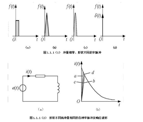
![]() And bipolar PWM
And bipolar PWM![]() It only changes in the unipolar range in a half cycle. Bipolar PWM means that the PWM waveform has a positive and a negative half cycle.
It only changes in the unipolar range in a half cycle. Bipolar PWM means that the PWM waveform has a positive and a negative half cycle.