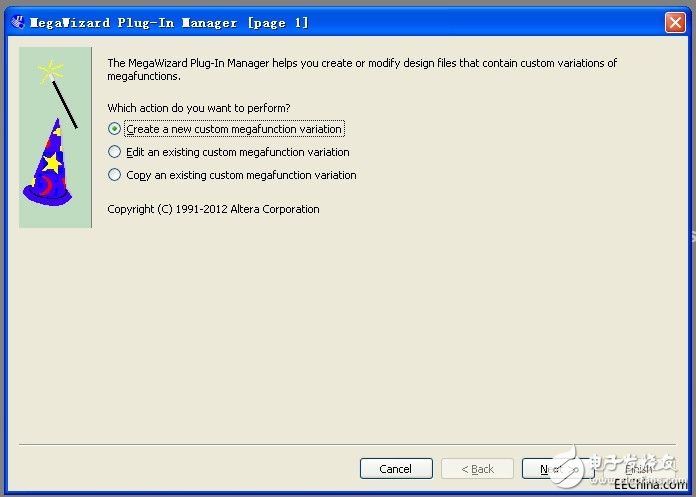
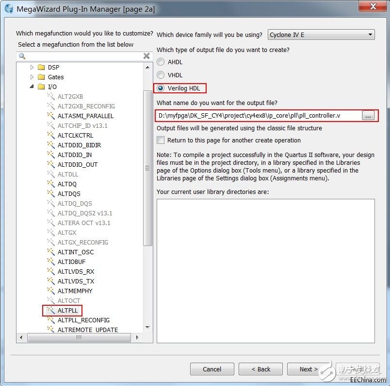
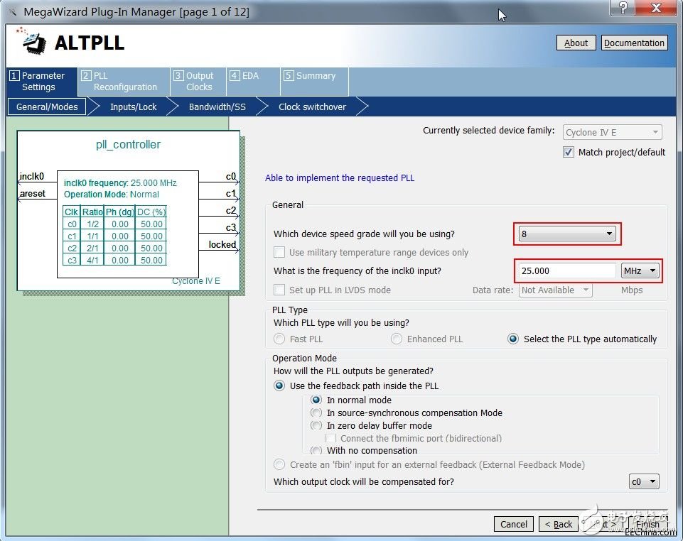
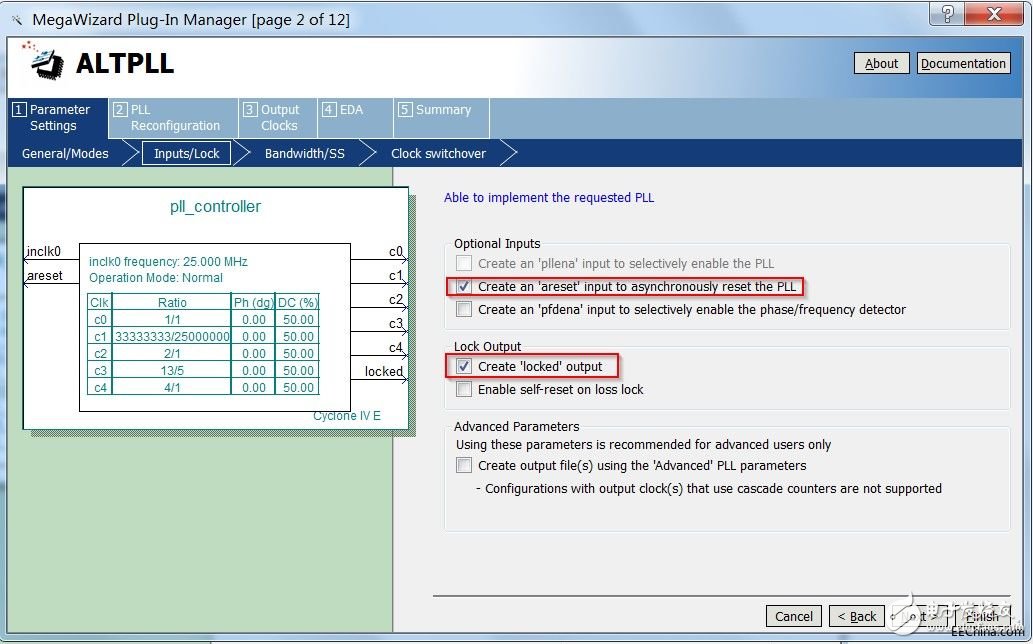
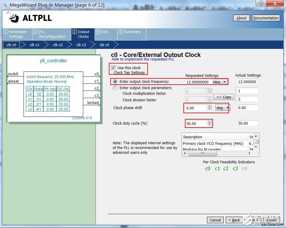
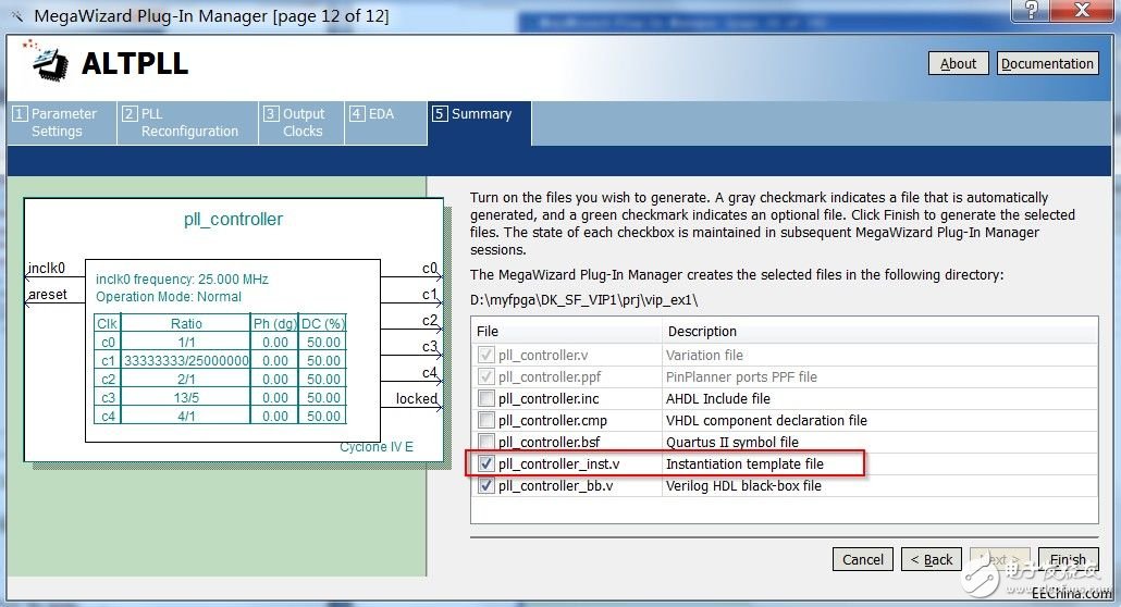
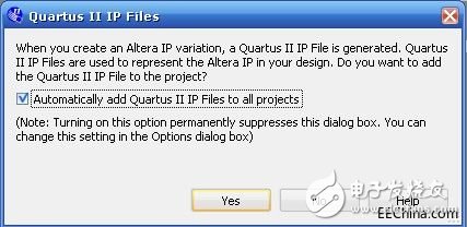
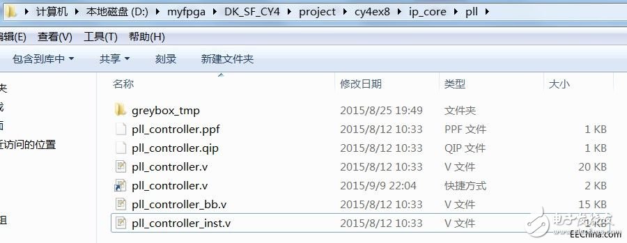
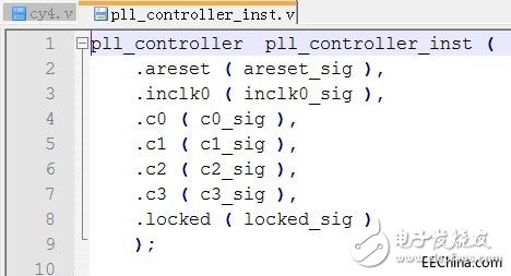
The entire project folder for the previous instance cy4ex7 can be copied and renamed cy4ex8. Then open this new project in Quartus II. Cyclone IV's PLL inputs a clock signal and can generate up to five output clocks. The frequency and phase of the output can be adjusted within a certain range. Below we look at how this example configures a PLL hard IP and integrates it into the project. As shown in Figure 8.18, click on the menu “Toolsà MegaWizard Plug-In Manager†in the newly created project. Figure 8.18 MegaWizard Menu As shown in Figure 8.19, select "Creat a new custommegafuncTIon variaTIon" and click Next. Figure 8.19 New IP Core Wizard Then select the IP core we need, set it as shown in Figure 8.20. â— Under Select a megafuncTIon from the list below, select the IP core as I/O à ALTPLL. â— In the drop-down box next to "What device family will you be using", select the device family we use as "Cyclone IV E". â— Under "What type of output file do you want to create?" select the language "Verilog". â— Under "What name do you want for the output file?", enter the path where the project is located, and add a name to the end. This name is the name of the PLL module we are instantiating. We can give him a name. Pll_controller, then click Next to go to the next page. The path it is here is actually the ip_core folder we created under the project folder cy4ex8 and the pll folder below it. Figure 8.20 Select ALTPLL as IP Core Then came to the PLL parameter configuration page, set as shown in Figure 8.21. Then click Next to go to the next page. â— Select "8" after "What device speed grade will you be using?", which is the speed grade of the device we are using. â— Select “25MHz†after “What is the frequency of the inclk0 input?â€, which is the reference clock frequency we input to this PLL. Figure 8.21 PLL General Configuration Page On the Input/Lock page, set it as shown in Figure 8.22, and then click Next to go to the next page. â— Check “Create an 'areset' input to asynchronously reset the PLLâ€, that is, the 'areset' signal of the PLL hard core is extracted. This is an asynchronous reset signal of the PLL hard core, and is active high. â— Check “Create 'locked' output†to get the 'locked' signal of the PLL hard core. This signal is used to indicate whether the PLL has completed internal initialization and can already output a valid high level. Figure 8.22 PLL Input/Lock Configuration Page The Bandwidth/SS, Clock Switchover, and PLLReconfiguraTIon pages do not need to be set. The default is. Directly enter the OuputClocks page, as shown in Figure 8.23, there are five selectable clock output channels. Turn on the corresponding clock output channel by ticking the Use this clock option under the corresponding channel. The frequency, phase, and duty cycle of the output clock can be set in the configuration page. Here is the setting of the C0 channel. â— Check Use this clock to use this clock output signal. â— Enter "Enter output clock frequency" is "12.5MHz", indicating that the channel output clock frequency is 12.5MHz. â— Input "Clock phase shift" to "0 deg", indicating that the phase of the clock output from this channel is 0 deg. â— Enter "Clock duty cycle (%)" to "50.00%" to indicate that the duty cycle of the clock outputted by this channel is 50%. Figure 8.23 ​​clk c0 configuration page for the PLL As with the configuration of C0, we can turn on and configure C1, C2, and C3 respectively. Although these routines are temporarily unavailable for these clocks, subsequent routines will be used. â— The clock frequency of C1 is 25MHz, the phase is 0deg, and the duty cycle is 50%. â— C2 clock frequency is 50MHz, phase is 0deg, and duty cycle is 50%. â— The clock frequency of C3 is 100MHz, the phase is 0deg, and the duty cycle is 50%. After the configuration is complete, at the bottom of the Summary page, as shown in Figure 8.24, check the *_inst.v file. This is a PLL instantiated template file. We can find this file in the project directory and open it later. Copy its code into the project, modify the corresponding interface to complete the IP core integration. Figure 8.24 PLL Summary Configuration Page Click Finish to complete the PLL configuration. If the dialog box shown in Figure 8.25 pops up in the project, check the option "Automatically add Quartus II IP Files to all projects" and click Yes. Figure 8.25 Add IP Core File to Project At this point, we can go to the pll folder, as shown in Figure 8.26, open the pll_controller_inst.v file, which is an instantiation template for this PLL IP core. Figure 8.26 PLL IP Core Generation File Pll_controller_inst.v is shown in Figure 8.27. Copy the contents of the file, and change the signal name in () to the interface signal name we connected to this module. Figure 8.27 PLL IP core instantiation template Product Description Diaphragm Seal Systems,Absolute Pressure Gauge,Analog Pressure Gauge,Manometer Pressure Gauge,Accutire Pressure Gauge Changshu Herun Import & Export Co.,Ltd , https://www.herunchina.com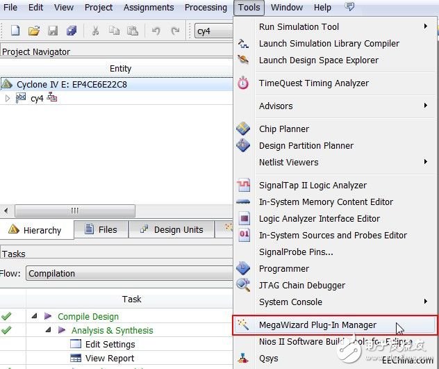
E-CHEN Diaphragm RO Booster Pump 802 Series
Diaphragm Seal Systems are economical pumps but still as powerful as the 103 series. The Absolute Pressure Gauge is a kit for pipe pressures up to 30 psi. Analog Pressure Gauge provides reliable outlet pressure, Manometer Pressure Gauge for efficient membrane utilization. Available in 50 and 75 GPD.