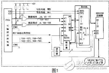
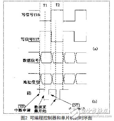
0 Preface Since the beginning of the 21st century, microelectronics and computer technology are developing rapidly. With this development, the speed and efficiency of PLCs have been greatly improved. For example, Toyota's FX2a series PLC is a good example. The PLC runs at a speed of 1 few hundred microseconds, and the basic command of this PLC is only 0.05μS. But from this PLC, we can easily see that it has reached a perfect level in all aspects, in addition to the efficiency of this PLC. High and fast, it also adds floating-point operations. For the addressing mode of this PLC, there are two main types, direct addressing and indexed addressing. In the execution of the entire PLC program, it is mainly divided into three stages, namely, inputting data, executing necessary programs, and outputting data. In the process of executing the program, the cycle is different because the length of the program is not equal. Assuming that a perfect monitoring system is to be produced, then a specific PLC must be selected to connect to the communication port, but in doing so, the corresponding cost will be high. This paper mainly analyzes the working principle of PLC system and the principle of dot matrix liquid crystal display monitoring system based on its own characteristics. First, the PLC software system circuit It can be clearly seen from Figure 1 that the output of the PLC is divided into two parts, one of which is dedicated to the remote control of the PLC; the other is used as the bus of the PLC. Among them, Y0-Y17 constitutes the data line DB, Y20-Y25 constitutes the address line, this address line and the PLC chip 82C55 are connected to each other, Y27 in the figure is the output control line of the whole PLC system, and Y27 is also the input of the single chip microcomputer. And output signals. From the figure, we can easily see that the 82C55 is the carrier of the PLC bus and the single-chip microcomputer. The 82C55 can precisely connect the single-chip microcomputer and the PLC software system. When the system reads in the information, all the information is the output data bus of the PLC, and all the information is read and written by the MCU. The interface of the liquid crystal display is carefully designed according to the interface control requirements of the display, and the liquid crystal display will be controlled by the single chip microcomputer and the PLC. From the figure we can see that the PLC actually has two sets of lines, which are the high-speed bus of the single-chip and the low-speed bus of the PLC software system. Regardless of the bus, they must pass through the 82C55 as a carrier to achieve the final data transmission. Second, the timing coordination and structure of the programmable controller If you want the data to be transmitted smoothly, then the PLC bus must be in accordance with the timing relationship. For the programmable controller, its scanning speed is very slow, its data and information can only get a new set of data after the end of the scanning cycle, its working efficiency is far less than the working efficiency of the microcontroller, in order to ensure the PLC Work efficiency, only through the chip interface, so that the information between the two buses can be transmitted to each other. If there is a new information waiting for output in the PLC software system, the Y27 in the figure will send an output information signal to the MCU, and the MCU will feedback the output information in the first time to execute the PLC information output program. From the timing diagram of the programmable controller and the single-chip microcomputer in Figure 2, we can intuitively see that Y17 is the control signal of the PLC, and also the application signal of the single-chip interrupt peripheral; from the previous discussion, we know that the data output signal of the PLC Very slow, when the MCU reads the data, in order to make it more accurate, when the MCU interrupts the program, it will generally delay 2-4MS as much as possible. When all the information and data are relatively stable, the MCU passes the 82C55 as the carrier. , read in the data. The purpose of this is to make the data and information of the programmable controller more stable, and to facilitate the more accurate reading of the information by the microcontroller. Swing Radiator,Power Transformer Swing Radiator,Swing Type Radiator,Distribution Transformer Swing Radiator Shenyang Tiantong Electricity Co., Ltd. , https://www.ttradiator.com
