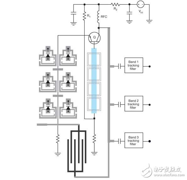
1 background Oscillator designers are now being asked to do more with less because more features and bands are being packaged into electronic communication products such as cellular phones and wireless local area network (WLAN) devices. Next-generation wireless communications should ideally have sufficient frequency flexibility to cover multiple frequency bands and numerous communication standards. This can be achieved using multiple oscillators, each of which has its own frequency tuning range. Another approach, as invented by Synergy Microwave's frequency source designer, is to build a single reconfigurable concurrent oscillator (RCO) that will cover multiple voltage-controlled oscillators (VCOs). Synergy's RCO can support multiple radio bands (Figure 1). Compared to separate oscillators, these RCOs provide the equivalent of independent tunable oscillators, while the size and power consumption are significantly reduced, making them suitable for multi-band, multi-mode wireless communication systems. Figure 1: This reconfigurable concurrent oscillator (RCO) can generate multiple signals for multiple radio bands. 2 Overview of Tunable Oscillator Design Efforts to miniaturize wireless communication hardware have led to the development of compact radio designs using tunable oscillators (such as VCOs) that cover many different frequency bands. However, tunable oscillators typically compromise between phase noise performance and power consumption. Attempts to develop multi-band VCOs with low phase noise often result in large, large power consumption circuits. There are a number of technologies designed to provide a compact frequency source solution for multi-band radio designs, including switching between independent VCOs, using linked multi-frequency circuits, or switching between multiple resonators. However, they inevitably have the disadvantages of large size, high power consumption, or poor phase noise performance. For example, switched resonators are often affected by the resistive and capacitive parasitic circuit components associated with the switch. The mode switching function is typically used to select between various modes of oscillation of the resonant circuit, and the selection is based on the fact that the loss and nonlinearity of the switch does not affect the steady state and phase noise performance of the resonator. However, this method does not produce signals concurrently, and has very limited effect in achieving frequency source size, power consumption, and design cycle reduction. Conventional band selection sources typically employ multiple resonators, VCOs, or other tunable oscillators, but any band selection switch inevitably reduces the performance of such multi-band sources. In Synergy Microwave's new approach, multi-band signals are generated concurrently and can be used as needed (Figure 2). Figure 2: RCO source method can be used when multiple concurrent signals are required, such as signals in the 2.4 GHz and 4 to 8 GHz range This new oscillator (Figure 1) uses a higher order multi-coupling planar resonator (MCPR) to generate different frequencies simultaneously for different frequency bands (and different applications). It does not require a frequency multiplier to operate, nor does it need to switch between the resonator and / or oscillator. Compared to other multi-signal generation methods, this approach reduces complexity, size and power consumption, and achieves superior phase noise performance (Figure 3). Figure 3: Multi-Signal Oscillator Method Reduces Power Consumption and Size Without Sacrificing Phase Performance Which communication device can benefit from this multi-signal source? Wireless local area networks (WLANs) are the most popular wireless applications in home and office environments, and they typically operate in different frequency bands—especially from the 2.4GHz to 2.5GHz industrial-scientific-medical (ISM) band and from 5.15GHz to 5.85. Various frequency bands of GHz. WLAN radios that can operate in both frequency bands can work with switchable VCOs, although a more fully integrated multimode radio design should work based on a single source (such as an RCO) that can cover both bands simultaneously. 3 Principles of multimode radio The basic principle of a multimode radio is to simultaneously process two or more signals of different frequencies using only one transmit/receive signal processing chain. Figure 4 shows the frequency planning of a dual-band, 2.4 GHz/5 GHz WLAN transceiver system. It uses a single 8 GHz VCO with a two-way divider in the frequency synthesizer to generate a 4 GHz signal, followed by a four-divider to obtain a 1 GHz signal. These sync (I) and quadrature (Q) signals are mixed in a quadrature single sideband (SSB) mixer to produce a 5 GHz signal, which is then further divided to obtain a 2.4 GHz signal. Figure 4: This frequency plan will generate multiple WLAN signals from a single 8GHz VCO This approach requires multiple buffers, dividers, and filter circuits to generate the signals needed for a dual-band WLAN radio. It is also possible to generate multiple signals by adding a frequency multiplier from a lower frequency signal. However, in the case of using a quadrature frequency converter, the multiplier is rarely used for the last stage of frequency conversion because it is very difficult to process the differential output at a higher frequency. 4 hardware design of multi-mode multi-frequency oscillator A conventional single output oscillator produces a periodic waveform that is essentially a fundamental frequency plus its harmonic signal components. A tunable oscillator based on a higher order resonator can provide multiple oscillation modes and can generate multiple independent frequencies individually or simultaneously. The single output tunable oscillator is a good starting point for designing multiband oscillators. A single frequency tunable wideband oscillator utilizes a second order resonator network tuned by a varactor to generate a signal of a particular frequency. It uses an active device (such as a bipolar transistor) to terminate the parallel or series inductance (LC) resonant tuning circuit. A parallel LC resonator network has a large parallel resistance (or anti-resonance), while a series LC resonator network provides a small series resistance (or resonance). The performance of such a design will inevitably be limited by the transistor capability, the electrical characteristics of its package, and the wide range of capacitance required to tune the oscillator over a wide frequency range. Zinc Alloy Support,Speaker Stands Zinc Casting,Desktop Speaker Stands Zinc Casting,Studio Monitor Stand Zinc Casting Dongguan Metalwork Technology Co., LTD. , http://www.diecast-pro.com


