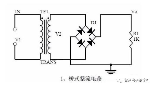
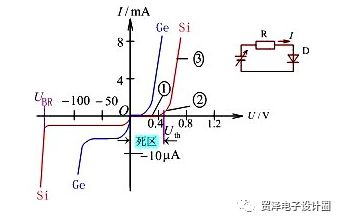
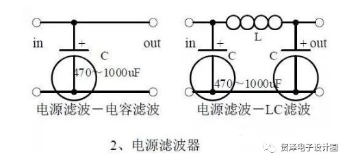
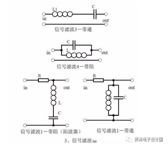
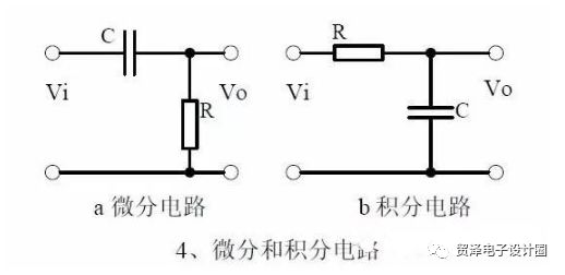
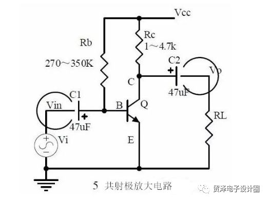
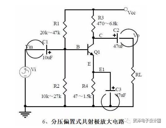
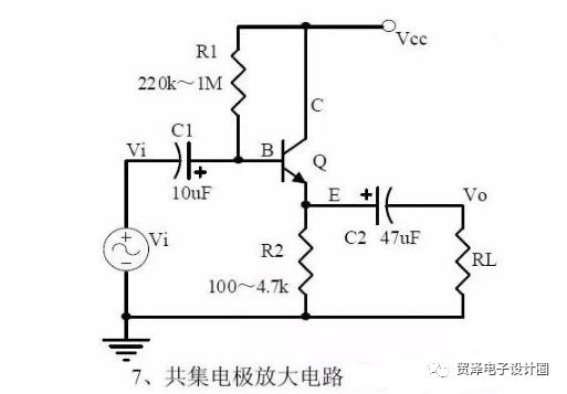
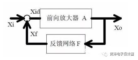
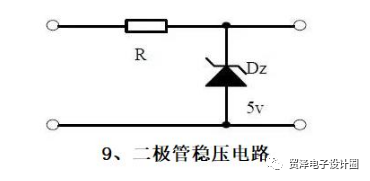
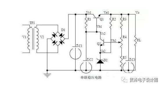
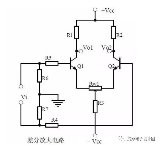
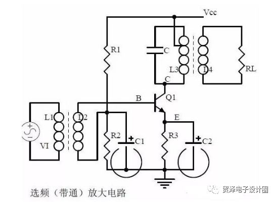
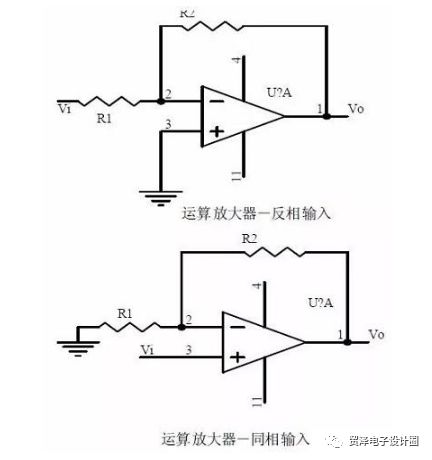
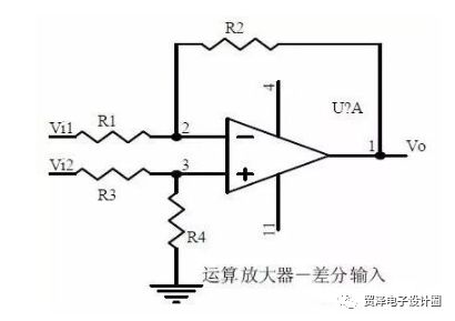
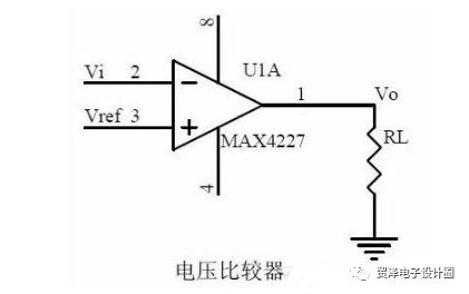
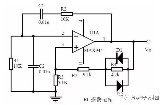
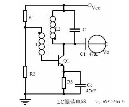
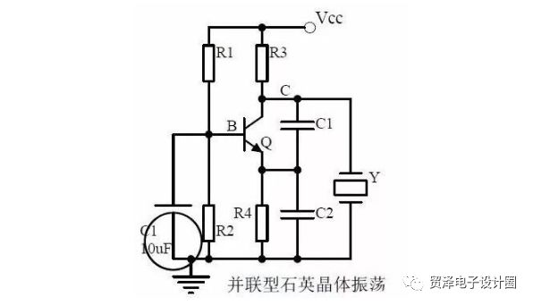
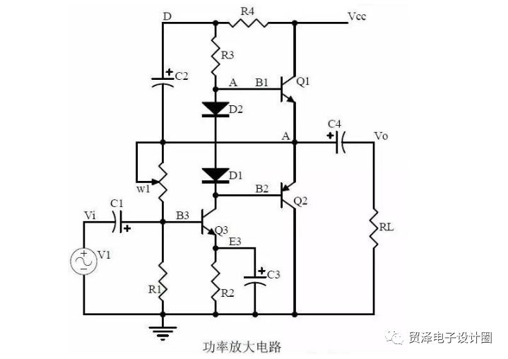
The analog circuit is divided into three levels: Primary level It is skillful to memorize these twenty circuits and it is clear what these twenty circuits do. As long as it is an electronic enthusiast, anyone who learns automation, electronics, and other electronic control professionals should and can remember these twenty basic analog circuits. Intermediate level Is able to analyze the role of the key components in the twenty circuits, each component failure when the circuit function is affected, the measurement of the parameters of the law of change, to master the treatment of fault components; qualitative analysis of circuit signals Flow direction, phase change; Qualitative analysis of signal waveform changes; Qualitative understanding of the circuit input and output impedance, the relationship between signal and impedance. With these circuit knowledge, you are very likely to grow into an outstanding maintenance technician for electronic products and industrial control equipment. Advanced level It is able to quantitatively calculate the input/output impedance of these twenty circuits, the ratio of the output signal to the input signal, the relationship between the signal current or voltage in the circuit and the circuit parameters, the relationship between the amplitude and frequency of the signal in the circuit, and the relationship between the phase and frequency characteristics. Selection of components and parameters in the circuit. After reaching the advanced level, as long as you are willing, well-respected high-paying occupations - the development and design engineers of electronic products and industrial control equipment will be your first choice. 1 Bridge rectifier circuit Note points: 1, the unidirectional conductivity of the diode: The diode PN junction plus forward voltage, in the conduction state; plus reverse voltage, in the cut-off state. Volt-ampere characteristic curve: Ideal switch model and constant pressure drop model: The ideal model is that when the diode is forward biased, its tube voltage drop is 0, and when it is reverse biased, its resistance is considered infinite, and the current is zero. The constant voltage drop model is that when the diode is turned on, the tube pressure drop is a constant value, the silicon tube is 0.7V, and the tube is 0.5V. 2, bridge rectifier current flow process: When u2 is a positive half cycle, the diodes Vd1 and Vd2 are turned on, and the diodes Vd3 and Vd4 are turned off, and the current of the load RL is the load flowing from top to bottom, and the voltage on the load is the same as that of the positive half cycle of u2. During the negative half of u2, the actual polarity of u2 is positive and negative. The diodes Vd3 and Vd4 are on and Vd1 and Vd2 are off. The current on the load RL is still flowing through the load from top to bottom, and the load is equal to the positive half of u2. The same period of voltage. 3. Calculation: Vo, Io, diode reverse voltage: Uo=0.9U2, Io=0.9U2/RL, URM=√2U2 2 Power filter Note points: 1. Process analysis of power supply filtering: The power supply filtering is to connect a larger capacity capacitor in parallel across the load RL. Since the voltage across the capacitor cannot be mutated, the voltage across the load will not be mutated, so that the output voltage can be smoothed and filtered. Waveform formation process: When the output terminal is connected to the load RL, when the power is supplied, the current is supplied to the load and also charged to the capacitor C. The charging time constant is τ charge=(Ri∥RLC)≈RiC, generally Ri<<RL, ignoring the voltage drop of Ri Influencing, the voltage on the capacitor will rise rapidly with u2, when ωt = ωt1, there is u2 = u0, then u2 is lower than u0, all diodes are cut off, the electric capacity C passes RL to discharge at this moment, discharge time constant is RLC, discharge time is slow, U0 changes slowly. When ωt = ωt2, u2 = u0, ωt2 after u2 changed again than u0, and began the charging process, u0 rise rapidly. When ωt=ωt3, u2=u0. After ωt3, the capacitor discharges through RL. This is repeated and periodically charged and discharged. Due to the energy storage effect of the capacitor C, the voltage fluctuation on the RL is greatly reduced. Capacitance filtering is suitable for applications where the current changes little. The LC filter circuit is suitable for applications where the current is large and the voltage ripple is required to be small. 2. Calculation: Filter capacitor capacity and pressure value selection The output voltage Uo of the capacitor filter rectifier circuit is between √2U2 and 0.9U2. The average value of the output voltage depends on the size of the discharge time constant. Capacitance capacity RLC≧(3~5)T/2 where T is the period of the AC mains voltage. In practice, it is often further approximated by the maximum reverse peak voltage of Uo≈1.2U2 rectifier URM=√2U2, and the average current of each diode is half of the load current. 3 Signal filter Note points: 1, the role of the signal filter: the unwanted signal components in the input signal is attenuated to a small enough extent, but at the same time must let the useful signal pass smoothly. Differences and similarities with power supply filters: The difference between the two is that the signal filter is used to filter the signal and its passband is in a certain frequency range, and the power filter is used to filter out the AC component and make the DC pass to keep the output voltage stable. The AC power supply is only allowed. A particular frequency passes. The same point: all work with the amplitude-frequency characteristics of the circuit. 2, LC series and parallel circuit impedance calculation, in series, the circuit impedance is Z = R + j (XL-XC) = R + j (ωL-1 / ωC) parallel circuit impedance when Z = 1 / jωC ∥ ( R+jωL) 4 Differential and integral circuits Note points: 1, the role of the circuit, and the difference between the filter and the same point. 2, differential and integral circuit voltage change process analysis, draw a voltage change waveform diagram. 3. Calculation: Time constant, voltage change equation, selection of resistance and capacitance parameters. 5 Common emitter amplifier Note points: 1, triode structure, triode current relationship, characteristic curve, amplification conditions. 2, the role of components, the use of the circuit, voltage amplification, input and output signal voltage phase relationship, AC and DC equivalent circuit diagram. 3, static operating point calculation, voltage amplification calculation. 6 Partial pressure biased common emitter amplifier Note points: 1, the role of components, the use of the circuit, voltage amplification, input and output signal voltage phase relationship, AC and DC equivalent circuit diagram. 2. The analysis of current series negative feedback process and the influence of negative feedback on circuit parameters. 3, static operating point calculation, voltage amplification calculation. 4. Controlled source equivalent circuit analysis. 7 Common-collector amplifier circuit (emitter follower) Note points: 1, the role of components, the use of the circuit, voltage amplification, input and output signal voltage phase relationship, AC and DC equivalent circuit diagram. Circuit input and output impedance characteristics. 2. The analysis of current series negative feedback process and the influence of negative feedback on circuit parameters. 3, static operating point calculation, voltage amplification calculation. 8 Circuit Feedback Block Diagram Note points: 1. The concept of feedback, positive and negative feedback and its judgment methods, parallel feedback and series feedback and judgment methods, current feedback and voltage feedback and their judgment methods. 2. Amplification gain with negative feedback circuit. 3, negative feedback on the circuit's amplification gain, passband, gain stability, distortion, input and output resistance. 9 Diode voltage regulator circuit Note points: 1, the characteristics of the voltage regulator diode. 2, Zener diode application considerations. 3, analysis of the voltage regulation process. 10 Series regulated power supply Note points: 1. The block diagram of series regulated power supply. 2, the role of each component; analysis of the regulation process. 3, the output voltage calculation. 11 Differential amplifier circuit Note points: 1, the role of various components of the circuit, the use of the circuit, the characteristics of the circuit. 2, the working principle of the circuit analysis. How to amplify differential mode signals and suppress common mode signals. 3, the circuit single-ended input and double-ended input, single-ended output and double-ended output mode of operation. 12 FET amplifier circuit Note points: 1. Classification, characteristics, structure, transfer characteristics and output characteristics of FETs. 2, the characteristics of the field effect amplifier circuit. 3, field effect amplifier circuit applications. 13 Frequency selective (band pass) amplifier circuit Note points: 1, the role of each component, the characteristics of the frequency-selective amplifier circuit, the role of the circuit. 2. Calculation of characteristic frequency, selection of frequency selective element parameters 3, amplitude frequency characteristic curve 14 Operational Amplifier Circuit Note points: 1. The concept of an ideal operational amplifier, a virtual short circuit at the input of the op amp, and a virtual circuit at the input of the op amp 2, the main purpose of the op amp circuit of the inverting input mode, the phase relationship between the input voltage and the output voltage signal 3. The gain expression (input impedance, output impedance) in the non-inverting input mode. 15 Differential input operation amplifier circuit Note points: 1, the characteristics of differential input operation amplifier circuit, use. 2. The relation between output signal voltage and input signal voltage. 16 Voltage comparison circuit Note points: 1, the role of voltage comparator and work process. 2. Comparator input-output characteristic curve diagram. 3, how to constitute a hysteresis comparator. 17 RC oscillator circuit Note points: 1, the composition of the oscillatory circuit, the role of the starting phase conditions, starting and oscillating oscillator oscillation amplitude conditions. 2, RC circuit impedance and frequency curve, phase and frequency curve. 3, RC oscillator circuit phase condition analysis and oscillation frequency. 18 LC oscillator circuit Note points: 1. Analysis of oscillation phase conditions 2, DC equivalent circuit diagram and AC equivalent circuit diagram 3, oscillation frequency calculation 19 Quartz crystal oscillation circuit Note points: 1, the characteristics of quartz crystal, equivalent circuit, characteristic curve. 2, the characteristics of quartz body vibrator 3, quartz crystal oscillator oscillation frequency 20 Power amplifier circuit Note points: 1, B class power amplifier work process and crossover distortion; 2. Composite rules of composite triodes; 3, Class A and Class B power amplifier work principle, bootstrap process, Class A power amplifier, Class A and Class B power amplifier features. How much is your "fever"? If you are burning at the beginning, then you must be able to remember these twenty circuits and be clear about the effect of these twenty circuits. If you are medium-fired, then you can analyze the role of the key components in the twenty circuits, what the function of the circuit is affected by each component failure, the change of the parameters when measuring, master the components of the fault The method of processing; You can also qualitatively analyze the flow of the circuit signal, phase changes, qualitative analysis of signal waveform changes, qualitative understanding of the circuit input and output impedance size, and signal and impedance relationship. If you have been able to quantitatively calculate the input and output impedances of these twenty circuits, the ratio of the output signal to the input signal, the relationship between the signal current or voltage in the circuit and the circuit parameters, the relationship between the amplitude and frequency of the signal in the circuit, and the relationship between phase and frequency Characteristics, selection of components and parameters in the circuit, etc. Congratulations, you are already a high fever 39.5 degree electronic engineer veteran! Plastic Tube Pressure Gauge,Plastic Pressure Gauge,Plastic Tube Manometer,Plastic Pipe Pressure Gauge ZHOUSHAN JIAERLING METER CO.,LTD , https://www.zsjrlmeter.com