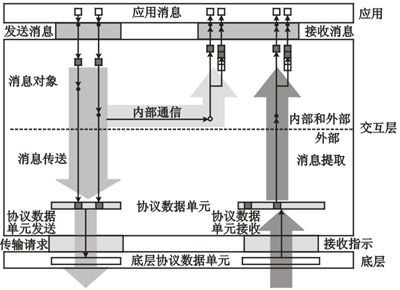
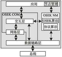
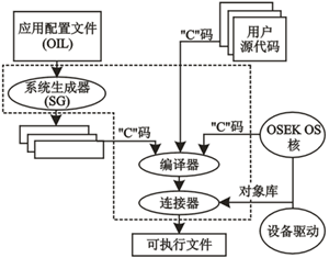
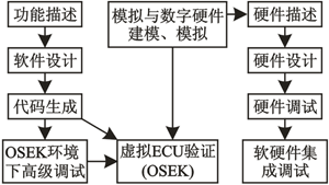
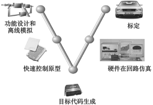
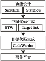
1 Introduction This article refers to the address: http:// Automotive electronics is one of the important signs of the development of modern automobiles. At present, the use of electronic devices in every car in the world has become a major indicator of the level of this car. In order to strengthen the market competitiveness, 16-32-bit microprocessors are widely used abroad, and more advanced sensors are widely used, so that the functions of automobiles are expanded from the control of the automobile itself to the "automotive-human-environment" system. Information acquisition, processing and control. 2 Classification of automotive electronic products and application of embedded technology According to the influence of the driving performance of the car, the automotive electronic products can be classified into two categories. One is car-controlled electronics - automotive electronic control devices. The automotive electronic control device should be used in conjunction with the on-board mechanical system, the so-called "electromechanical combination" of automotive electronic devices. They include engine, chassis, and electronic control of the body, such as electronic fuel injection systems, anti-lock braking control, anti-skid control, traction control, electronically controlled suspension, electronically controlled automatic transmission, electronic power steering, and more. The other type is in-vehicle electronics - in-vehicle automotive electronics. The vehicle-mounted electronic device is an electronic device that can be used independently in an automobile environment, and is not directly related to the performance of the automobile itself. They include automotive information systems (driving computers), navigation systems, car audio and television entertainment systems, in-vehicle communication systems, and Internet access devices. The technical basis of automotive electronics is embedded technology. In the past few decades, embedded technology has developed rapidly. With the advent of the post-PC era, computing is widely embedded in applications, and embedded systems will become the main way of computing in the future. The evolution of the traction and computing environment of the application has driven the development of embedded technology. The combination of embedded technology and industry has also driven the development of the industry. The electronic and informationalization of automobiles is the application of embedded technology in the automotive industry. Vehicle-controlled electronic products are functional unit devices such as electronic control units (ECUs) and smart sensors (Smart Sensors) distributed in automobiles. These devices are connected together by a bus to form a subsystem. They can communicate in a protocol that suits them, such as Lin, J1939, and so on. Different subsystems also form a larger network through the bus. Smart Sensor is a unified body of sensors and transmitters based on industrial fieldbus, with CPU as the processing core and digital communication as the transmission method. Compared to traditional Sensors, Smart Sensor adds digital communication capabilities to the network and has networking capabilities. 3 Vehicle Control Electronic Product System Platform - OSEK/VDX In order to meet the needs of the development of increasingly large and complex automotive electronic control software, the portability of application software and the compatibility between control modules of different manufacturers are realized. In 1993, the German automotive industry jointly introduced the open system and interface of the automotive electronics - OSEK/VDX (Open Systems and the Corresponding Inte RFaces For AutomoTIve Electronics) specification, which aims to provide an open structure for the distributed control unit on the car. Industry standard. The OSEK/VDX specification provides a more comprehensive definition and regulation of the electronic control software development platform for automobiles from the real-time operating system RTOS (RealTime Operating System), software interface, communication and network management. The whole set of solutions proposed by it is the development direction of future automotive electronic software development. At present, some companies have introduced operating systems that comply with the OSEK/VDX specification and have been certified by the OSEK/VDX committee, such as OSEK Works, OSEKOS, OSEKTurbo, etc. The OSEK/VDX standard includes the following four parts: OSEK/VDX operating system specification (OSEK OS), OSEK/VDX communication specification (OSEK Communication, OSEK COM), OSEK/VDX network management specification (OSEK Network Management, OSEK NM) ) and the OSEK/VDX implementation language (OSEK OIL). Using an embedded real-time operating system that conforms to the OSEK/VDX standard can increase the reuse rate of product code, reduce development costs, and shorten product development cycles. The application architecture of an embedded real-time operating system compatible with the OSEK/VDX standard is shown in Figure 1. Figure 1 Operating system application architecture compatible with OSEK/VDX specification The operating system part (OS), communication part (COM), network management part (NM), implementation language part (OIL), and operation debugging interface part (ORTI) of the OSEK specification are respectively introduced below. 3.1 OSEK OS Specification The OSEK OS specification defines the implementation mechanism and application programming interface (API) of the operating system kernel, including task management mechanism, interrupt handling mechanism, event mechanism, resource management mechanism, alarm management mechanism, and related standard application programming interfaces. The implementation mechanism of the OSEK OS specification can be found on the website 3.2 OSEK COM Specification The OSEK COM Specification provides a unified communication environment for automotive ECU applications. The OSEK COM specification improves the portability of application software modules by defining application software communication interfaces as well as ECU internal communication and ECU external communication. OSEK COM provides a variety of services to facilitate the transfer of data between tasks and tasks, between interrupt service routines and interrupt service routines, and between tasks and interrupt service routines. The purpose of the OSEK COM specification is to support the portability, reusability and mutual cooperation of application software. The application interface hides the distinction between internal and external communication, as well as different communication protocols, bus systems, and networks. Communication in OSEK COM is message based. The message includes data for a specific application. Message and message properties are statically configured via OSEK Implementation Language (OIL). The content and usage of the message is not related to OSEK COM. OSEK COM allows zero length messages to exist. In the case of internal communication, the interaction layer IL (Interaction Layer) causes the message data to be immediately sent to the receiver. In the case of external communication, the IL compresses one or more messages into designated Interlayer Protocol Data Units (IPDUs) and passes them to the lower layer processing, as shown in Figure 2. The functionality of internal communication is a subset of the functionality of external communication. The message manager in the interaction layer is based on the message object. The message object exists on the sender side as "send message object", and on the receiving end is "receive message object". Figure 2 Simple model for message transmission and reception in OSEK COM The data of the interaction layer and the lower layer communication are organized as I-PDUs, including one or more messages. A message must occupy consecutive bits in the I-PDU and cannot be separated, crossing in the I-PDUs. Messages are bit aligned in I-PDUs. The size of the message is stated in bits. The interaction layer provides an application programming interface (API) to process messages, and the API includes initialization, data transfer, and communication management services. The service that delivers messages over the network is non-blocking, and a service that sends messages may not be able to return a final delivery state because the transmissions in the network are still in progress. OSEK COM provides a notification mechanism for applications to determine the status of a transmission or reception. 3.3 OSEK NM Specification For automotive ECU products produced by different manufacturers, they have a tendency to connect to a network through serial data exchange. Therefore, in order to avoid duplication of effort and shorten development time, a basic standard is required. The OSEK Network Management System specification provides a network connectivity standard for improving the network interconnection capabilities of ECU products. The purpose of the OSEK NM task is to improve the security and reliability of ECU product network communications. The OSEK NM specification specifies the mechanisms and application programming interfaces (APIs) for network management. ECU products using the OSEK NM specification have the following features: ◆ After authorization, each node must be accessible; ◆ Maximum tolerance is allowed in cases where access is allowed to fail; ◆ Support network diagnosis. As a basic configuration, a network management implementation that adheres to the OSEK specification must be applied to all nodes of the network. Each node can obtain status information of the entire network at regular intervals. OSEK NM provides two mechanisms for network monitoring: one is to monitor the application's messages for indirect monitoring; the other is to directly monitor the specific network management using the tagging mechanism. OSEK NM includes the following sections: ◆ OSEK NM interface with the application (API); ◆ Algorithm for node monitoring; ◆ OSEK NM and OSEK COM interface; ◆ Algorithm for transitioning to sleep state; ◆ OSEK NM Protocol Data Unit (NMPDU). Figure 3 illustrates the location of the OSEK NM throughout the system and its relationship to other parts. Figure 3 Location of the OSEK NM in the system 3.4 OSEK implementation language specification To achieve software portability goals, the OSEK Implementation Language Specification defines a way to configure and use OSEK applications. Figure 4 shows an application development process that adheres to the OSEK specification. OIL files can be handwritten or generated by system configuration tools. Figure 4 Application development process based on OSEK specification OIL provides a mechanism for configuring OSEK applications in a specific CPU. Each CPU corresponds to an OIL description, and all OSEK system objects are described by OIL objects. The OIL description of an OSEK application is a combination of a set of OIL objects, and the CPU is a container for these OIL objects. OIL explicitly defines all standard attributes for each OIL object. Each OSEK application can define additional special execution attributes and references. Each OSEK application can limit the range of values ​​for each attribute. Objects in the OIL include: CPU (processor), OS (operating system), Appmode (application mode), Isr (interrupt service), Resource (resource), Task (task), Counter (counter), Event (event) ), Alarm, Com (communication subsystem), Message (message), Ipdu (interaction layer protocol data unit), NM (network management). 3.5 OSEK ORTI Specification The OSEK ORTI Specification (OMEK Run-Time InteRFace Specification) provides a unified interface for OSEK operating system development tools. With OSEK ORTI, debugging tools can capture and display information such as the operating state and performance of the operating system, the status of various tasks, and the status of various operating system objects. ORTI files are generated by the system generator during the system generation phase. ORTI uses the KIOL language to pass operating system kernel information to the debugger, while defining some syntax rules for the OSEK standard object. ORTI information is provided via an ASCII text file. Since OSEK/VDX is based on static configuration, ORTI does not support dynamic representation and configuration data. The OSEK ORTI specification includes Part A and Part B: Part A introduces the language of the operating system kernel object defined by ORTI for debugging tools (Kernel Object Interface Language, KOIL); Part B describes the OSEK/VDX standard objects, attributes and them. The meaning. 3.5.1 ORTI file structure The ORTI file contains a version information section, a declaration section, and an information section. The version information section describes the version of KOIL and the kernel. For ORTI, the kernel version is the version number of the ORTI standard. The declaration section declares the type of kernel used in the ORTI implementation, which is equivalent to the structure declaration in the C language. It describes the way to access the data contained in a kernel object. This section details the display name for a given attribute. The information section contains the methods declared in all of the given system declaration sections, describing the methods for calculating or referencing the required properties. The information section also provides static values ​​and expressions for the required attributes. 3.5.2 Standard ORTI Objects and Attributes An OS object that contains properties such as a running task, a running priority, a running interrupt handler, an operating system service, a recent error, a currently applied schema, and so on. A task object that contains attributes such as priority, status, stack, activity status, and context. A context object that contains two attributes: address, size, and so on. The stack object contains four attributes: size, base address, stack direction, and fill mode. The alarm object contains five attributes such as alarm time, period, status, action, and counter. A resource object that contains three attributes: status, resource lock, and priority. The message container object contains five attributes: message name, type, queue size, queue counter, and current message address. 4 Development process of vehicle-controlled electronic products Vehicle-controlled electronic products are embedded systems that combine hardware and software. In order to save resources and shorten the product development cycle, software and hardware synchronization development solutions should generally be adopted, as shown in Figure 5. The development tools of vehicle-controlled electronic products provide good support for the simultaneous development and debugging of software and hardware. The software development of vehicle-controlled electronic products is divided into functional description, software design, code generation, and advanced debugging in the operating system environment. The hardware development of vehicle-controlled electronic products is divided into hardware description, hardware design, hardware debugging and other steps. After the software design is completed, the verification on the virtual ECU platform is completed by using the corresponding tools. After the hardware design is completed, the hardware and software integration debugging is performed together with the hardware. Through this development method, the time to market is shortened. Figure 5 Software and hardware parallel development solution At present, the car vehicle control electronic product software development process is a "V" shape development process, as shown in Figure 6. The "V" shape development process is divided into five phases, namely functional design, prototype simulation, code generation, hardware-in-the-loop simulation - HIL, calibration. Figure 6 car control electronics product development process The main tool used in the functional design phase is MATLAB. Through the use of tools such as Simulink and Stateflow provided by MATLAB, the tasks of control scheme design, function module design, and control algorithm design are completed, and preliminary simulation work is performed. The main tool used in the prototype simulation phase is DSPACE. Offline simulation was done using the RCP tool provided by dSPACE. Before starting this phase, you need to use Real Time Workshop, Targetlink and other tools to complete the conversion of code generated by Simulink, Stateflow, etc. to standard C code. In the process of converting to standard C code, an embedded real-time operating system conforming to the OSEK specification can be added as needed. The main tool used in the code production phase is CodeWarrior. The conversion of standard C code to product code on the target hardware platform is accomplished by using tools such as compilers and debuggers provided by CodeWarrior. Figure 7 shows the code generation process for a vehicle-controlled electronic product. Figure 7 car control electronics product code generation process Conclusion China's independent development of automotive vehicle control products is still in its infancy. This paper briefly introduces the OSEK/VDX specification of the vehicle control product system platform, and presents a simple vehicle control electronic development model based on the OSEK/VDX specification. In this model, developers are required to use the international mainstream development tools to improve development efficiency and shorten development time. 3V Lithium Fluorocarbon Series Batteries
3V Lithium Fluorocarbon Series Batteries use fluorocarbon material as the battery positive electrode. The fluorocarbon material has high thermal and chemical stability. It does not decompose at high temperature ≤600℃, and does not crystallize at low temperature. The battery operating temperature range can reach -40~125℃ ; Its chemical stability ensures the safety of the battery, so that the battery has a higher safety performance when short-circuit, collision, and extrusion, and has the characteristics of explosion-proof and spontaneous combustion. Our company uses self-developed electrolyte to make the battery life more than 10 years.
3V Lithium Fluorocarbon Series Batteries,Cells Coin Cells For Computer Motherboard,Wide Working Temperature Rang Coin Batterise,Coin Cells Long Lasting For Toys Shandong Huachuang Times Optoelectronics Technology Co., Ltd. , https://www.dadncell.com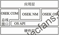
Our BR series button batteries are conventional high and low temperature resistant button batteries, and the working temperature is -40℃~+85℃
Accepts customized upgraded version of high and low temperature resistant button battery, working temperature is -40℃~ +125℃
Battery application range: It can be used in fields that have strict requirements for high and low temperatures and high energy density. For example, automobile tire pressure gauge (TPMS) battery, industrial control motherboard battery, computer motherboard battery, smart instrument battery, oil field drilling platform emergency equipment power supply, marine life-saving flasher, implantable medical battery, etc.
Vehicle Control Electronics Development Based on OSEK/VDX Specification
google_protectAndRun("ads_core.google_render_ad", google_handleError, google_render_ad);