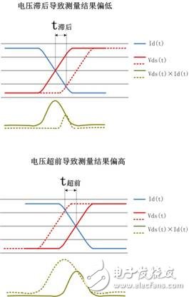
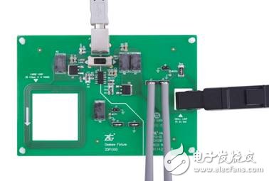
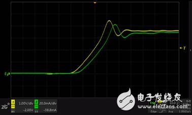
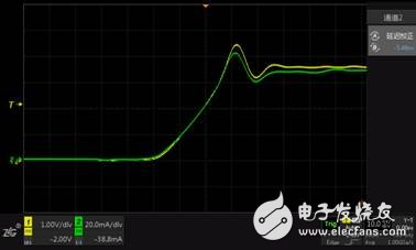
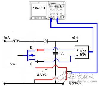
The power loss of switching devices is an important part of the evaluation of switching devices, and it is also an advanced analysis function for many oscilloscopes. In fact, although many laboratories are equipped with a power loss measurement environment, the equipment and probes are also expensive, but if the time offset is ignored, all test results will be meaningless. What issues should be considered in switching loss measurement? In the actual measurement evaluation, we use one channel to measure the voltage, the other channel to measure the current, then the software multiplies the power curve, and then integrates the time interval to get the final result. Two points to note in this: Ensure that the oscilloscope and probe have sufficient bandwidth to accurately obtain the waveform of the switching device during the turn-on and turn-off processes; Accurately measure the phase and ensure the correspondence between voltage and current. Ample bandwidth is better understood, but how do we guarantee the correspondence between voltage and current? The effect of time offset on measurement results When there is a time offset between the voltage channel and the current channel, the measurement result is obviously higher or lower, and the faster the switching speed of the device, the more obvious the influence of the offset. REF _Ref430694484 h Figure 1 is a schematic diagram of the turn-off loss measurement of the MOS tube. It can be seen that the correct measurement result can only be obtained after correction. It is worth noting that this offset is ubiquitous due to the difference between the implementation of the voltage and current probes and the length of the probe transmission cable. Figure 1 The effect of the offset between channels on the measurement results How to correct the channel offset? As shown in Figure 2 of REF _Ref430697056 h, the offset correction fixture can directly correct the time offset between the voltage probe and the current probe. The basic principle is that the fixture generates a set of pulse signals of voltage and current with zero phase difference simultaneously on the voltage and current probes, observes the time offset of the pulse signal after passing the probe through the oscilloscope, and corrects the offset time on the oscilloscope. The fixture is powered by the USB interface and is easy to use. The correction of the time offset can be done manually or automatically. Using the offset correction fixture, the waveforms before and after correction are shown in Figures 3 and 4, respectively. Figure 2 ZDF1000 offset correction fixture Figure 3 Waveform before offset correction Figure 4 Offset corrected waveform Effect of extension lines on transmission delay In addition to performing offset correction, in the actual measurement, attention should also be paid to the effect of the extension line. A typical test schematic is shown in Figure 5. Since the current clamp usually cannot measure the current directly on the PCB, the current needs to be drawn through the extension cable. The extension cable introduces a transmission delay. The ordinary copper extension cable can be calculated at 33.5 ps/cm and the oscilloscope delay correction parameter. Make compensation. Similarly, the extension of the voltage probe will also bring the transmission delay, which can be compensated according to the lead delay relationship in the actual measurement. Taking Figure 5 as an example, assuming that the length of the extension line is 100 cm, the delay time of the current channel is: 33.5 ps/cm & TImes; 100 cm = 3.35 ns. After the calibration is done using the offset correction fixture, the delay correction time of the current channel should be adjusted to lead the voltage channel by 3.35 ns. Figure 5 Typical test schematic From the above analysis, it can be seen that when using the oscilloscope to measure the switching loss of the high-speed switching device, in addition to ensuring accurate waveform measurement of the voltage channel and the current channel, it is also necessary to pay attention to the time offset between the channels, which is introduced by the probe. The time offset, which introduces a large error into the measurement itself. Therefore, when accurately estimating the power loss, be sure to correct the channel delay using the offset correction fixture. Lens Hood,Lens Accessories,Camera Lens Hood,Camera Hood Shaoxing Shangyu Kenuo Photographic Equipment Factory , https://www.kernelphoto.com