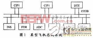
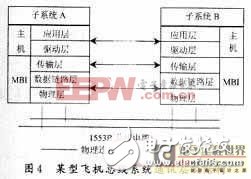
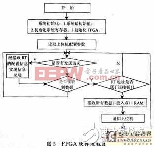
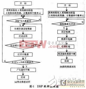
At present, with the advancement of processes and technologies, the development of integrated circuit technology has made it possible to integrate a Programmable System ON a Chip (PSOC) on one chip. Among them, Field Programmable Gate Array (FPGA) has been widely used in the design of mathematical ASIC due to its flexible design and high speed. The theory and implementation of digital signal processing (DSP) has developed rapidly and has become one of the fastest growing disciplines in the world. Due to its high speed processing speed and powerful and flexible interface and communication capabilities, it has been widely used in many fields [1]. The MILSTD1553B data bus has bidirectional output characteristics, real-time and high reliability, and is widely used in modern transport aircraft and a large number of civil airliners and military aircraft. 1 1553B data bus system composition The 1553B bus system is mainly composed of three parts: bus controller BC; remote terminal RT; data bus D ata Bus. The bus system of an aircraft is constructed as shown in Figure 1. In the figure, CIP1 is BC, CIP2 is CIP1 backup, other subsystems are RT, and the bus system is double redundant, and the two sets of buses are backups of each other. This article refers to the address: http://TIcle/241686.htm CIP1 is a communication and information processing system; CIP2 is a communication and information processing system backup; DTE is a data transmission device; INS is an inertial navigation system; FDR is a flight parameter recording system; ADC is an atmospheric data computer; IFU is an interface component; FCC is a fire Control computer; SMS is the external management system; LRS is the laser ranging system. 2 1553B data bus communication protocol The 1553B bus operates at 1 Mb/s. Adopt Manchester II code, half-duplex working mode. The main hardware components are the bus controller (BC), the remote terminal (RT) and the optional bus monitor (MT). In general, these three parts are completed by a multiple bus interface (MBI). The MBI can be embedded in the computer. The bus has 10 message formats. Each message contains at least 2 words, each word has 16 message bits, 1 parity bit and 3 bit length sync headers. All message words are composed of Manchester II code. The format of the word transmitted by the data bus of 1553B is shown in Figure 2. The 1553B data bus uses an instruction/response communication protocol. He has three types of terminals, namely: (1) Bus controller (BC) He is the only terminal on the bus that is scheduled to perform the task of establishing and starting data transfers. (2) Remote terminal (RT) He is the interface of the user subsystem to the data bus, which extracts data or absorbs data under the control of BC. (3) Bus monitor (MT) He "monitors" the transfer of information on the bus to complete the recording and analysis of the data source on the bus, but he does not participate in the bus communication itself. 3 1553B data bus message transmission format The transfer of information on the 1553B bus is in messages. All messages consist of data words, instruction words, and status words. The following are the 10 message formats allowed by the 1553B protocol, as shown in Figure 3. 4 A certain aircraft bus system communication hierarchy Referring to the ISO seven-layer model of open interconnection system, an aircraft airborne system is divided into five layers: application layer, driver layer, transport layer, data link layer and physical layer, as shown in Figure 4. The functions of these five layers are clearly defined and the interface is simple, which lays a good foundation for the design and implementation of hardware and software [2]. The application layer is the highest level of the communication system. It implements communication system management functions (such as initialization, maintenance, reconstruction, etc.) and interpretation functions (such as describing the meaning, validity, scope, format, etc. of data exchange). The driver layer is the software interface between the application layer and the lower layer. In order to realize the application layer management function, the driver layer should be able to control the initialization, start, stop, connect, disconnect, start its own test of the multiplex bus interface (MBI) in the subsystem, monitor its working status, control its and son Data exchange of the system host. The transport layer controls data transmission on the multiplex bus, and the tasks of the transport layer include information processing, channel switching, and synchronization management. The data link layer controls the transmission sequence of messages on the bus as specified by MILSTD1553B. The physical layer handles bitstream transmission on the 1553B bus physical medium as specified by MILSTD1553B. The application layer and the driver layer are implemented on each subsystem host, and the transport layer, the data link layer, and the physical layer are implemented on the MBI. 5 bus system communication software design In the design of an aircraft aviation bus system, a very important task is the design of bus communication software. The design of the aviation bus communication software includes: software design of the driver layer and the application layer. The driver layer directly drives the bus interface board to complete the configuration of each register to realize data transmission and reception; the application layer is the highest layer in the design, and he manages the functions of the entire system [3]. As an interface board, the design focuses on the design of the driver layer software. It includes three aspects: (1) Software in the FPGA part. (2) Software in the DSP part. (3) PC operating system driver software. 5.1 FPGA program control function This part is written in VHDL language, which realizes the functions of receiving and transmitting 1553B bus data, Manchester II code, error detection, parity check, interface with DSP and decoding circuit. The transmitting unit and the receiving unit work in parallel and are implemented by logic gate circuits. Here is a flow chart drawn from the software perspective as shown in Figure 5. 5.2 DSP program control function The functions implemented by the DSP control part program are as follows: (1) Initialization of the bus interface board (including initializing the internal circuit of the DSP itself and the register FPGA and the host computer communication register). (2) Realize RT address recognition Since it is a multi-RT bus interface board, after receiving the data, it should be determined whether the RT address belongs to the interface board; (3) with the host computer message transmission control function The message transmission control program completes the data exchange between the bus interface board and the host computer for the data to be transmitted by the bus. Including the data read and write process and the self-test process, the operations to be completed are as follows: 1 Write the transmit data (to the bus) to the FPGA. 2 Read data from the FPGA (this data is processed by the DSP). 3 Write data to the dual port RAM (to the host computer). In: 0px auto; ""4 self-test process. The self-test process is to implement the data transmission and reception performance test of the interface board after receiving the self-test command of the host computer. (4) Interrupt control program In the design of the DSP chip TMS320F206 interface, three hardware interrupts are used, INT1 and INT2 are generated by the FPGA, and INT3 is generated by the host computer. INT1 indicates that the receiving unit of the FPGA has received a data, and informs F206 to read. INT2 indicates that the receiving unit of the FPGA has received an error data, and informs F206 to read the error status information. INT3 is a kind of data transmission control of the upper computer and the interface board. Means, through the INT3 interrupt, the host computer tells the interface board whether to receive data or data, how much data is sent, the message format used, and the bus control. The DSP part of the software is mixed programming in C++ and assembly language. The key paths are interrupt service programs, data transmission and receiving programs use assembly language to achieve maximum execution efficiency, and the main program is written in C++. The flow chart of the DSP part software is shown in Figure 6. 5.3 PC control program It mainly realizes software driver, data communication and transmission control of the interface board of the host computer under a specific operating system. Mainly use C++ to develop software in Windows environment. 6 conclusion This paper introduces a method based on FPGA and DSP for the design and implementation of communication software for a certain aircraft bus system. In the actual application, the bus system communication function is better realized, which has certain use and reference value for the 1553B bus research.
Hot selling Minsound series ceiling speakers produce clear and loud sound of high-fidelity in a wide coverage.
We have different models of ceiling speakers with different power ,speaker unit and size,
It is ideal choice for home theatre, meeting room, shopping mall, lecture room,classroom and so on.
Ceiling Speaker,Ceiling Loudspeaker,in Ceiling Speaker,in Ceiling Speakers,Ceiling Mount Speakers Taixing Minsheng Electronic Co.,Ltd. , https://www.ms-speakers.com