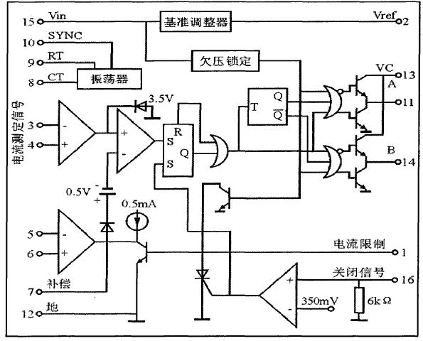
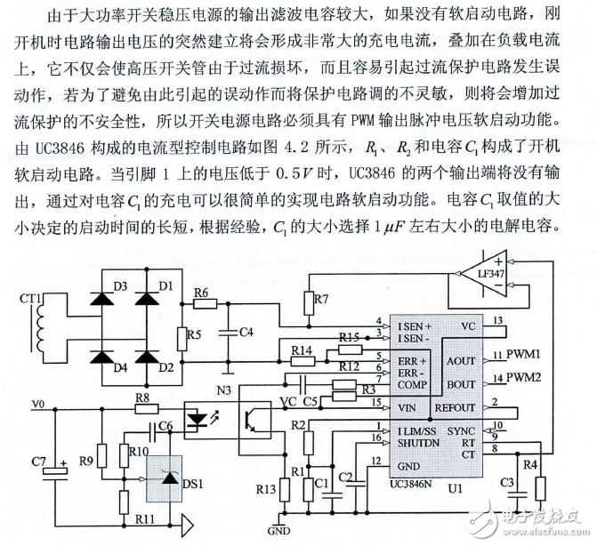
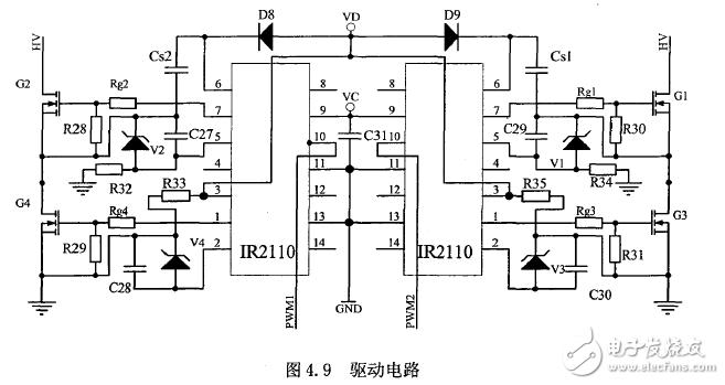
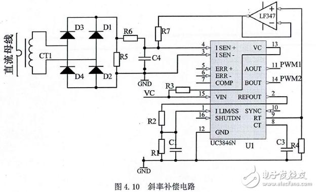
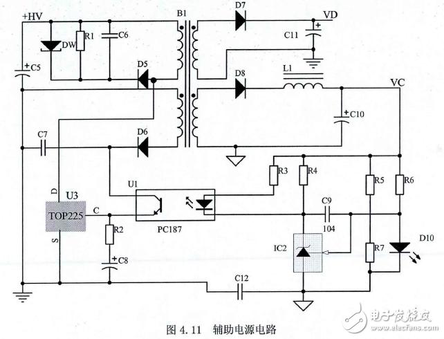
The control circuit of the full bridge topology designed in this paper mainly includes controller, protection circuit, current feedback, voltage feedback, drive circuit and auxiliary power supply. The control circuit is the core part of the switching power supply. Its design is very important for the performance of the switching power supply. Many indicators of the power supply such as constant voltage constant current, ripple size, input and output characteristics are closely related to the control circuit, and at the same time, the main circuit It is a full-bridge topology. When designing the control circuit, it is necessary to take corresponding measures to prevent the shoot-through phenomenon. The following is a detailed design and introduction of the functional circuits of each part of the control circuit. UC3846 is used as the control chip. The chip uses a high current totem pole type double-ended output, output peak current up to 500mA, can directly drive the FET, built-in precision bandgap adjustable reference voltage, high frequency oscillator, error amplifier, differential current sense amplifier, owed The voltage lock circuit and the boot soft start circuit have an automatic shutdown function. Its main advantages are current limit, automatic feedforward compensation, undervoltage protection, terminal lock protection, and better load response characteristics. The peripheral control circuit is simple and the operating frequency is up to 500KHZ. The maximum input voltage is 40V and the reference voltage output is typically 5.1V. The internal structure is shown in the figure. Figure UC3846 internal structure block diagram Figure UC3846 control circuit diagram In high-power circuits, current transformers are often used to detect current. Current transformer detection can not only improve efficiency, but also achieve electrical isolation, which is an ideal choice. Based on the above, this paper selects the current transformer to detect the primary current. as the picture shows. The switching power supply relies on the voltage feedback control loop to ensure stable output voltage under different load conditions. This paper uses a voltage external loop feedback circuit composed of a precision voltage regulator TL431 and a photocoupler PC817. As shown in the figure, the TL431 is a A three-terminal adjustable voltage reference with good thermal stability can set any value in the range of 2.5~36V through different ratios of external two resistors. In order to achieve effective isolation between power ground and output ground, this paper chooses good linearity. The photoelectric coupler is isolated. The drive circuit is connected to the control circuit and the main circuit. It is an important part of the power supply. In the circuit where the main circuit is powered by high voltage, in order to ensure personal safety and good operation of the control circuit, a drive circuit with electrical isolation function is often used. There are two methods of isolation: transformer isolation and optocoupler isolation. The advantage of transformer isolation is that no separate power supply is required, and the delay is small. The main disadvantage is that the transformer is easily saturated when the output is wide pulse. The photoelectric isolation driving circuit has the advantages that the output waveform is good, and the disadvantage is that an independent auxiliary power supply is required. This article uses IR2110 photoelectric isolation driver, its structure is shown in the figure, its floating power supply adopts bootstrap boost circuit, which can realize the isolation of the main circuit of control circuit, and has small volume, fast speed and simple structure. High system stability and other advantages. There are two main ways to add the slope compensation circuit. One is to add the slope compensation signal to the inverting input of the error amplifier, and subtract the slope compensation signal from the error voltage signal, as shown in the figure. The other is to apply a slope compensation signal to the non-inverting input of the current amplifier, and add a slope compensation signal to the current detection signal as shown. This article uses an improved second method, as shown. A voltage follower is connected to the non-inverting input of the oscillator and the current amplifier, and the function is to reduce the influence of the current feedback on the oscillating circuit, and at the same time, improve the anti-noise capability of the oscillating circuit. In this paper, the auxiliary power supply adopts the flyback topology power supply composed of the three-terminal integrated device TOP225. As shown in the figure, since the control circuit and the drive circuit have different grounding positions, in order to effectively achieve electrical isolation, the auxiliary power supply adopts two output designs and output voltage. Both are 15V. The VC supplies power to the control circuit and the anti-surge protection circuit, and the VD supplies power to the drive circuit. R1, D5, and C6 form an RCD snubber circuit that absorbs the voltage spike generated when the switch is turned off. New Smart Watch New Smart Watch everyone enjoys luck , https://www.eeluck.com Introduction to current control chip
Soft start circuit
Current sampling and voltage sampling circuit
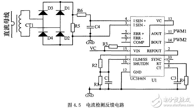
Voltage sampling circuit

Drive circuit
Slope compensation circuit design
Auxiliary power circuit design
Supercapacitor voltage equalization strategy based on multiple SEPIC chopper circuits
0 times
Window._bd_share_config = { "common": { "bdSnsKey": {}, "bdText": "", "bdMini": "2", "bdMiniList": false, "bdPic": "", "bdStyle": " 0", "bdSize": "24" }, "share": {}, "image": { "viewList": ["qzone", "tsina", "tqq", "renren", "weixin"], "viewText": "Share to:", "viewSize": "16" }, "selectShare": { "bdContainerClass": null, "bdSelectMiniList": ["qzone", "tsina", "tqq", "renren" , "weixin"] } }; with (document) 0[(getElementsByTagName('head')[0] || body).appendChild(createElement('script')).src = 'http://bdimg.share. Baidu.com/static/api/js/share.js?v=89860593.js?cdnversion=' + ~(-new Date() / 36e5)];