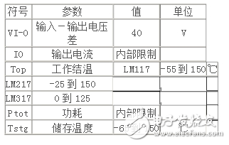
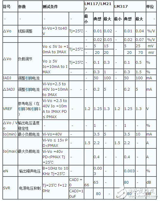
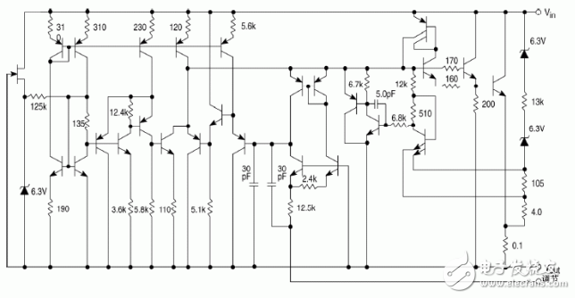
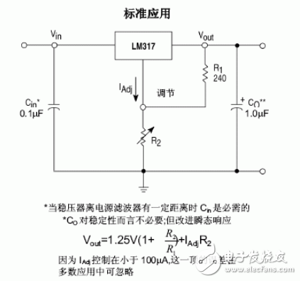
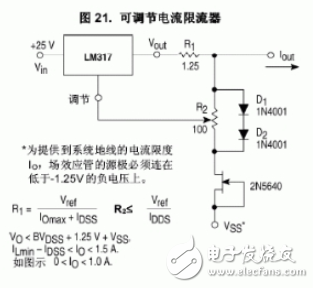
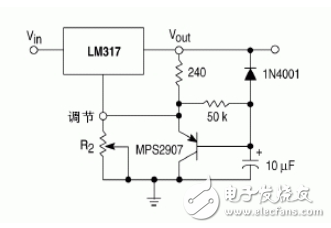
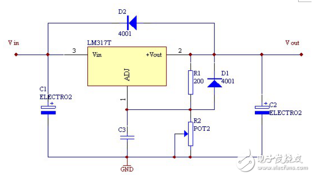
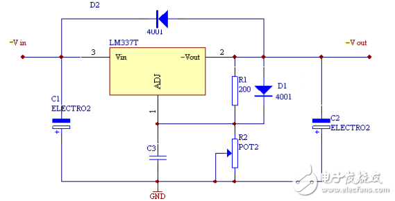
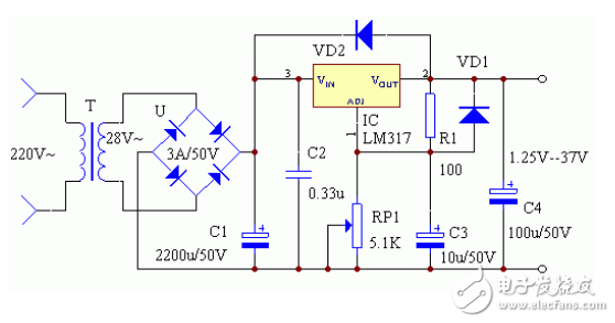
The LM317 is National Semiconductor's three-terminal adjustable positive regulator IC. The LM317's output voltage range is 1.2V to 37V and the load current is up to 1.5A. It is very simple to use and requires only two external resistors to set the output voltage. In addition, its linear regulation and load regulation are better than standard fixed voltage regulators. The LM317 has built-in protection circuits such as overload protection and safety zone protection. Usually the LM317 does not require an external capacitor unless the input filter capacitor is more than 6 inches (approximately 15 cm) from the LM317 input. Using output capacitors can change the transient response. Using the filter capacitor on the regulation side results in a much higher ripple rejection ratio than the standard three-terminal regulator. The LM317 can have many special uses. For example, suspending the adjustment terminal to a higher voltage can be used to regulate voltages up to several hundred volts as long as the input and output voltage difference does not exceed the limit of the LM317. Of course, avoid shorting the output. It is also possible to connect the trim terminal to a programmable voltage for a programmable power supply output. Adjustable output voltage as low as 1.2V Guaranteed 1.5A output current Typical linear adjustment rate of 0.01% Typical load regulation rate of 0.1% 80dB ripple rejection ratio Output short circuit protection Overcurrent, overheat protection Adjustment tube safety work area protection Standard three-terminal transistor package. The LM317 is continuously adjustable from 1.25V to 37V. The input voltage of the LM317 is more than 30 volts, and the output voltage is 1.5----32V. . Current 1.5A. . However, pay attention to power consumption when using it. . Pay attention to the heat problem. The LM317 has three pins. One input and one output for one voltage regulation. The input pin inputs a positive voltage, the output pin is connected to the load, and the voltage adjustment pin has one pin connected to the resistor (about 200) on the output pin, and the other is connected to the adjustable resistor (several K). The input and output pins are connected to the filter capacitors to ground. Figure 1 Basic LM317 regulated power supply circuit positive voltage output type Figure 2 Basic LM337 regulated power supply circuit negative voltage output type Figure 3 Complete LM317 regulated power supply circuit positive voltage output type The output current of the LM317 is 1.5A, and the output voltage can be continuously adjusted between 1.25-37V. The output voltage is determined by two external resistors R1 and RP1. The voltage difference between the output terminal and the regulation terminal is 1.25V. This voltage will be generated. A few milliamps of current, through R1, RP1 to ground, the voltage divided on RP1 is added to the adjustment terminal, and the output voltage can be changed by changing RP1. Note that in order to obtain a stable output voltage, the current through R1 is less than 3.5 mA. The LM317 consumes a maximum of 2W without a heat sink, plus a 200&TImes;200 &TImes;4mm3 heatsink with a maximum power consumption of 15W. VD1 (IN4002) is a protection diode that prevents the output of the regulator from short-circuiting and damages the IC. VD2 (IN4002) is used to prevent input short-circuit and damage the integrated circuit. When installing, note that capacitor C2 should be close to the input of the IC, and C3 should be close to the output of the IC, which can better suppress ripple. Its output voltage is continuously adjustable from 1.25-37V, and the maximum output current can reach 1.5A.
Many people do not know what kind of cameras are invisible cameras, and do not know how to distinguish invisible cameras, so here is how to distinguish invisible cameras.
USB Charger Camera,HD 1080P Camera,HD 720P Camera,4K Camera,Night Vision Camera,wifi Camera Jingjiang Gisen Technology Co.,Ltd , https://www.gisentech.com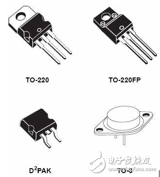
Invisibility, as the name suggests, means that it is not easy to be seen or found, so where do such cameras exist? In fact, invisible things are hidden by the external environment, so they will not be discovered. Such invisible cameras are generally hidden in things that are more difficult to see, such as: inside the socket, inside the TV, inside the stereo, inside the fan, etc. Cameras can be hidden in various household appliances. Why should they be hidden in electrical equipment? The main reason is that these equipments have power supply and will not be used because the camera cannot be powered.
LM317 regulator introduction, pin diagram, parameters, working principle and application circuit diagram
First, LM317 regulator introduction, pin diagram, parameters, working principle and application circuit diagram---LM317 introduction