Power-down protection Introduction Power-down data protection is an important function of system equipment. Transfer files for [membrane switch] proofing Transfer files for [membrane switch] proofing Transfer files for [membrane switch] proofing Transfer files for [membrane switch] proofing Use modern information technology to accurately grasp the growth process and growth dynamics of poultry, conduct dynamic monitoring and trend analysis of poultry at various growth stages, and provide fast and efficient remote guidance for poultry breeding, house management and epidemic prevention and slaughter, and improve the ability of fine breeding and house management, timely detection of problems in breeding, formulate technical countermeasures for poultry breeding and house management, put forward poultry breeding and house management opinions or suggestions, and better carry out technical guidance to promote poultry production. Livestock Health Monitoring device,Animal Health Monitoring System,Livestock Diet Monitoring Device eSky wireless Inc , https://www.eskygpsiot.com
At present, there are two main methods for power-down data protection:
(1) Add sufficient capacity spare battery to continue working after the system is powered off;
(2) Without the backup battery, the data to be protected when the power is turned off is stored in non-volatile memory such as FLASH and EEPROM.
The first method is bulky, expensive, and has a short battery life; the second method is simple, but the life of the erase device is limited. This paper proposes an improved method based on the second one, that is, using LM358 as a voltage comparator, the data is written into the EEPROM when the system is detected to be powered down. This method not only realizes the protection of system data power-down, but also prolongs the life of EEPROM.
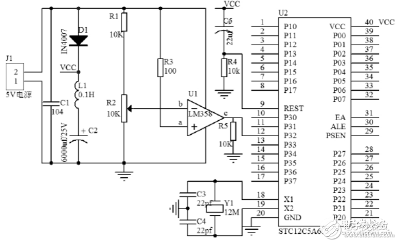
Design of Power-off Protection Circuit of Single Chip Microcomputer Based on LM358 
As shown in Figure 1, when the system is normally powered by adjusting R2, Ua"Ub=3.5V, the c terminal outputs a high level; when the system is powered down, the LM358 is not powered due to the isolation of the diode D1. Due to the presence of capacitor C2 and inductor L, capacitor C2 and inductor L1 continue to provide short-term power to the microcontroller, and due to the presence of pull-down resistor R5, the c-side outputs a low level. Used to trigger the microcontroller INT0 interrupt.
According to the STC12C5A60S2 series of microcontroller data, the time required to write one byte to the EEPROM and erase one sector are 55μs and 21ms, respectively. Typical power consumption is 2mA-7mA in normal mode. The effective minimum voltages for EEPROM operation of 5V MCU and 3.3V MCU are Umin=3.7V and Umin=2.4V respectively.
After the system is powered down, the equivalent circuit model is the RLC series circuit. The differential equation of the circuit during the discharge process is:
According to the parameter values ​​of R, L and C, it can be divided into under-damped oscillation state, critical damping state and over-damping state. The above equations can be divided into the following three types:
In summary: When the load R is constant, select the appropriate capacitor and inductance (C 2 =6600uf/25V, L 1 =0.1H). The specific parameters of L 1 and C 2 can be obtained by experimental tests. As long as uc (t) decays from the initial state of uc (t)| t=0 to uc (t)| t=t0 =U min for longer than the time t0 required to maintain the trigger interrupt to operate the EEPROM Job requirements.
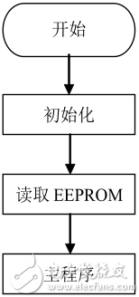
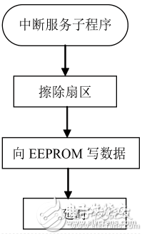
The main program of the MCU software design and the interrupt service subroutine flow chart are shown in Figure 2 and Figure 3, respectively. 
Figure 2: Main program 
Figure 3: Interrupt Service Routine
The procedures related to this design are as follows:
Void main(void)
{
??
Byte_Read(Address);
While(1)
{??}
}
Void INT0_int()interrupt 0
{
Sector_Erase(Address);
Byte_Program(Address,Date);
Delay(XX); //delay to ensure system reliability }
Analysis: When the system is powered down, the INT0 interrupt is triggered and the EEPROM is erased and written in the interrupt service subfunction.
Summarize the implementation of the system, applied to the two-dimensional motion control platform. When the system is powered down, the X-axis and Y-axis coordinates and other parameters are written to the EEPROM. After the system is powered on again, the X-axis and Y-axis coordinates stored in the EEPROM and other parameters are read out, and the working platform continues to move along the original set position with the position as the starting point.
The core of this paper is based on LM358 as a voltage comparator. It detects the EEPROM erasure when the system is powered down, avoiding the problem that the EEPROM is erased once every time the program is executed, resulting in short life. The soft and hardware structure is simple in design, which improves the practicability of the system.
This article gives a typical application with good portability. Adding a loop statement can store multiple data in EEPROM or read from EEPROM.
Collect valuable like animal body temperature, shed temperature, humidity, ammonia concentration, individual animal diet data, estrus indicators of female animals, abnormal changes in weight, and even individual animal mood indicators, etc.
These are not just data. They can be analyzed and excavated in depth through system and software integration, which can provide a basis for the farm to make better decisions, realize intelligent management, and increase operating income.