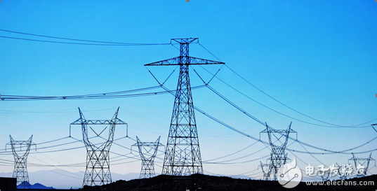
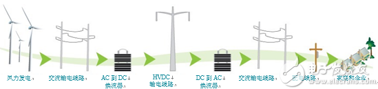
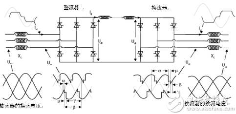
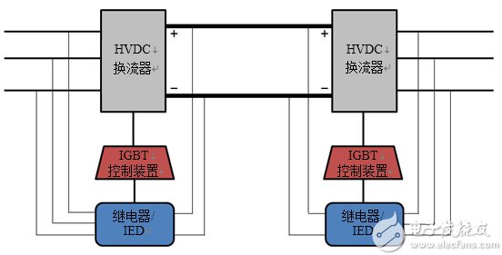
According to the US Energy Information Administration, the average retail price of US energy in 2014 was 10.44 cents/kWh, and the transmission and distribution loss was expected to be 5%. This loss value seems to be low, but this must take into account that the total net power generation in the United States is 4.1 trillion megawatt hours. In this case, 5% loss means more than 200 billion kWh and $21 billion in losses, so efforts to improve power transmission are our priorities. High-voltage direct current (HVDC) transmission is one of the solutions implemented to reduce transmission and distribution losses. Why is HVDC more efficient than conventional AC transmission? The loss of the HVDC transmission line is 30-50% less than that of the AC line of the same voltage. HVDC can increase the power factor when the voltage and current become out of phase. Because DC does not have a frequency associated with it, it is unaffected by the skin effect and can reduce the total power transmitted over the line. When the current density is concentrated on the surface or "outer skin position", the skin effect occurs and it gradually becomes sparse as it moves toward the center of the conductor. The higher the current density along the surface, the higher the effective resistance of the AC. HVDC also improves the reliability of the network. Certain types of HVDC stations can help stabilize asynchronous networks. So how is such a large amount of electricity transmitted to your home nationwide? Power is first transmitted from the source and transmitted to the converter station where it is upgraded to the required voltage before being rectified to DC voltage. The power can then be transferred as a HVDC over long distances to another converter station where it is reconverted to AC, and certain types of converter stations have the added benefit of controlling active and reactive power. The transformer then raises the AC power to the desired voltage to transfer and distribute the voltage to the home and/or factory as needed. Figure 1 shows this complete process. Figure 1: Transmission process (transmission line picture provided by Duke, USA) The most common types of converter stations are the grid commutated inverter (LCC) and the voltage source converter (VSC). Grid commutation converter Most HVDC systems currently in operation use an LCC topology. LCC is slightly more efficient than VSC and can transmit a larger amount of power. Its typical voltage level is 450kV or 500kV; however, China has several 800kV lines. Due to the use of pulse width modulation (PWM) technology, LCC does not exhibit switching losses like VSC. The LCC uses a thyristor as a switching device. A plurality of thyristors are connected in series to form a single line of a three-phase rectifier, which constitutes a so-called "valve". Since the thyristor can only be turned on and cannot be turned off, the AC voltage reverses the thyristor and stops conduction. Therefore, the bias of the thyristor in the LCC depends on the power used by the AC side of the grid for commutation. The delay in conduction when the thyristor is forward biased determines the phase angle delay (trigger angle). The phase angle delay of the thyristor achieves phase angle control of the alternating wave. LCC has two typical architectures: a 6-pulse bridge and a 12-pulse bridge. Figure 2 shows a 6-pulse bridge that uses six thyristor valves: two valves per phase to conduct positive and negative voltage waveforms. The harmonic response capability of the LCC is very poor. To compensate for this, harmonics can be improved by forming two 12-pulse bridges in series to form a 12-pulse bridge. Figure 2: LCC configuration (image courtesy of EE web) By analyzing the signal, you can control the waveform of the incoming and outgoing converters. Properly analyzing the signal allows the system to know the voltage and current levels as well as the power factor and to help determine if there are any faults on the line. Protection relays or intelligent electronic devices (IEDs) analyze signals. See Figure 3. Figure 3: Signal interpretation TI has several design guidelines that introduce signal analysis methods. The reference design for measuring AC voltage and current in a protective relay using Delta-Sigma chip diagnostics discusses how to acquire an output signal by using a current transformer, voltage divider, or Rogowski coil. This signal is then adjusted by isolated and non-isolated op amps to increase amplitude and reject any common-mode voltage and noise. The conditioned signal is then analyzed by the ADC. The digitized information obtained from the ADC is passed to the MCU for interpretation. Information determined from the waveform is fed back to the control of the inverter, which adjusts the changing phase and voltage levels to maintain stability. 230V Single Color Led Strip,Single Colour Led Strip Lights,Led Single Colour Dimmer,Led Strip Single Color NINGBO SENTU ART AND CRAFT CO.,LTD. , https://www.lightworld-sentu.com