Details of the new integrated digital temperature and humidity sensor from Sensirion Sensors. The sensor uses CMOSens patented technology to seamlessly combine temperature and humidity sensors, A/D converters and digital interfaces, making the sensor small in size, fast in response, simple in interface and cost-effective. This article combines examples to explain the command and timing of the sensor, and its application in the microcontroller system. Key words: SHT10; temperature and humidity sensor; digital sensor; ATmeg8L Introduction With the continuous development of society, people have entered the era of digital information, and the requirements for quality of life are getting higher and higher. Automobiles, air conditioners, dehumidifiers, dryers, etc. have become household names, and they are inseparable from environmental and temperature requirements. Sensirion of Switzerland introduced the SHTxx single-chip digital temperature and humidity integrated sensor. CMOSens technology is used to ensure high reliability and long-term stability. The sensor consists of a capacitive polymer moisture sensor and a bandgap temperature sensor, and seamlessly combines with a 14-bit A/D converter and a 2-wire digital interface in a single chip. The product has the advantages of low power consumption, fast response and strong anti-interference ability. 1 Features of SHT10 The main features of the SHT10 are as follows: ◆ Relative humidity and temperature measurement have dew point output; ◆All calibration, digital output; ◆Simple interface (2-wire), fast response; ◆Ultra low power consumption, automatic sleep; ◆ Excellent long-term stability; ◆Ultra small volume (surface mount); ◆ Wetness measurement accuracy ± 45% RH, temperature measurement accuracy ± 0.5 ° C (25 ° C). 2 pin description and interface circuit (1) Typical application circuit The typical application circuit of SHT10 is shown in Figure 1. The power supply voltage of the SHT10 is 2.4V to 5.5V. After the sensor is powered on, it will wait 11ms to recover from the "sleep" state. No instructions are sent during this time. A 100nF capacitor can be added between the power supply pins (VDD and GND) for decoupling filtering. (3) Serial interface The SHT10's two-wire serial interface (bidirectional 2-wire) is optimized for sensor signal reading and power consumption. The bus is similar to the I2C bus but not compatible with the I2C bus. 1 serial clock input (SCK). The SCK pin is the synchronous clock for the MCU to communicate with the SHTIO. Since the interface contains full static logic, there is no minimum clock frequency. 2 serial data (DATA). The DATA pin is a three-state gate for data transfer between the MCU and the SHT10. The state of DATA changes after the falling edge of the serial clock SCK and is valid on the rising edge of SCK. During data transfer, when SCK is high, the DATA data line must remain stable. To avoid data collisions, the MCU should drive DATA to a low state, and an external pull-up resistor pulls the signal high. 3 commands and timing (1) SHT10 command The SHT10 commands are listed in Table 1. Send a set of "Transport Start" sequences for data transfer initialization, as shown in Figure 2. The timing is: DT flip keeps low when SCK is high, then SCK generates 1 pulse, then DATA flip keeps high when SCK is high. (3) Measurement timing (RH and T) “000 00101†is the relative humidity (RH) amount, and “000 00101†is the temperature (θ) measurement. After sending a set of measurement commands, the controller waits for the measurement to end. This process requires approximately 20/80/320ms for its 8/12/14 bit measurement. The measurement time varies with the speed of the internal crystal and can be reduced by up to 30%. SHT10 pulls DATA low to put it into idle mode. The controller must wait for this "data ready" signal before restarting the SCK clock to read the data. Next, 2 bytes of measurement data and 1 byte of CRC check are transmitted. The MCU must acknowledge each byte by pulling DATA low. All data starts from the MSB and is valid for the LSB. For example, for 12-bit data, the value at the 5th SCK clock is used as the MSB bit; and for 8-bit data, the 1st byte (high 8 bits) data is meaningless. After confirming the CRC data bit, the communication ends. If the CRC-8 check is not used, the controller can end the communication by holding the ACK bit high after measuring the LSB bit of the data. (4) Reset timing If the communication with the SHT10 is interrupted, the serial port can be reset by a subsequent sequence of signals, as shown in Figure 3. Keep DATA high, trigger the SCK clock 9 times or more, and then send a set of "Transmit Start" sequences before executing the next command. These sequences only reset the serial port and the contents of the status register remain. The SHT10 implements an initial state setting through a status register. The read status register timing is shown in Figure 4. 1 CRC-8 check. The entire data transfer process is guaranteed by an 8-bit check to ensure that any erroneous data can be detected and deleted [1]. 2 In order to maintain its own heating temperature rise of less than 0.1 ° C, the activation time of SHTxx does not exceed 10%. Such as 12-bit accuracy measurement, measuring up to 2 times per second. 3 conversion to physical quantity output relative humidity output conversion formula is: When the measured temperature differs greatly from 25 °C, the temperature coefficient of the sensor needs to be considered: 5 SHT10 and ATmegal application examples Here is an example of the application circuit and control program of the ATmega8L (internal 8MHz oscillation frequency) MCU interface of SHT10 and Atmel's low-power 8-bit RISC instruction set. In this example, the SHT10 is controlled by an ATmega8L microcontroller, and the temperature and humidity data is read, and the result is displayed on the LCD 1602 (using 4-bit mode), as shown in FIG. 6.
Description
-Contact Resistance:≤50mΩ
â—† Small Compact Size, high reliability Rotating Switch,Rotary On Off Switch,Rotary Power Switch,Round Rotary Switch Ningbo Jialin Electronics Co.,Ltd , https://www.donghai-switch.com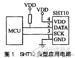
(2) Power supply pin (VDD, GND) 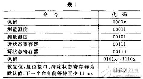
(2) Command timing 
The next command consists of 3 address bits (only "000" is supported) and 5 command bits. SHT10 indicates that the timing of correctly receiving the command is: DATA is pulled low (ACK bit) after the falling edge of the eighth SCK clock, and DATA is released after the falling edge of the ninth SCK clock (this time is high) ).
After the measurement and communication ends, the SHT10 automatically enters the sleep mode. 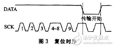
(5) Status register read and write timing 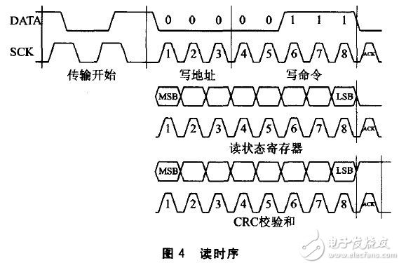
The write status register timing is shown in Figure 5. 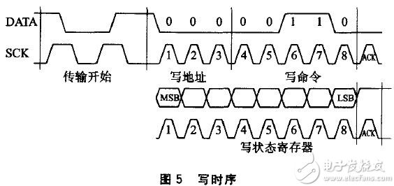
4 notes 
Among them, RHlinear is the linear value of relative humidity at 25 °C, SORH is the relative humidity value of the sensor output, c1, c2, c3 are coefficients, as listed in Table 3. 
Where RHtrue is the actual value of the relative humidity when the temperature is not equal to 25 ° C, θc is the current temperature, and t1 and t2 are the coefficients, as listed in Table 4. 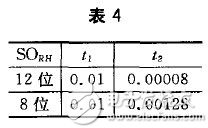
The temperature output conversion formula is: 
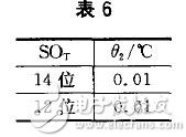
Where θ is the actual temperature, SOθ is the temperature value of the sensor output, and θ1 and θ2 are the coefficients, as listed in Tables 5 and 6. 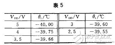
Since humidity and temperature are measured via the same chip, the SHT10 can simultaneously achieve high quality dew point measurements. The specific algorithm can be found in reference [2], which will not be described in detail here. 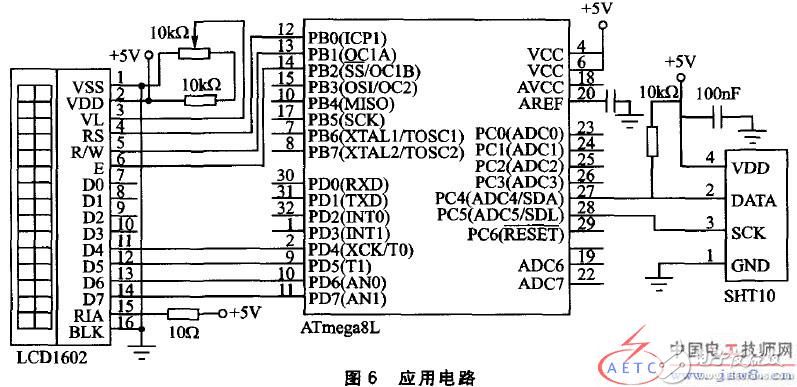
The program adopts C language modular design, which is greatly convenient to be transplanted to other MCUs for use, which improves work efficiency.
-Insulation Resistance:≥100mΩ
-Dielectric Strength:1,500V,
-1min Electronic Life:10,000 cycles
-Operating temperature:T120
-Rating current/voltage:6A 250V AC
Features
â—† Micro contact gap,High speed operation,High sensitirity,Micro operatizon travel.
â—† Long life & high reliability