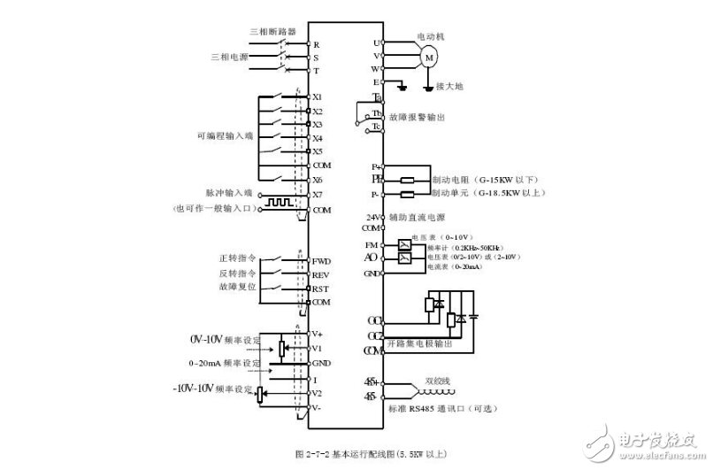
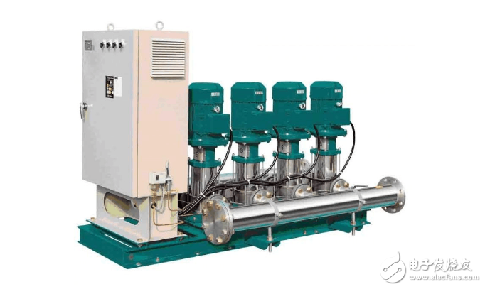
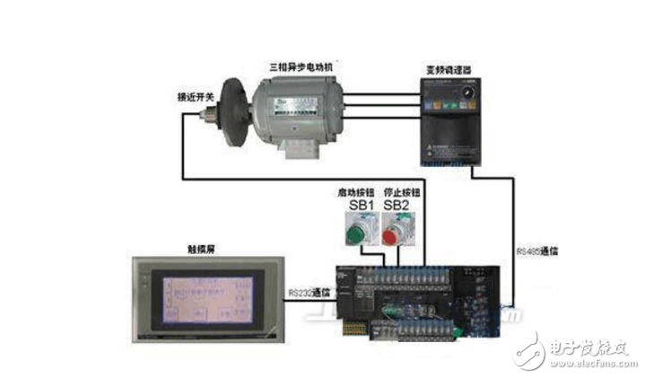
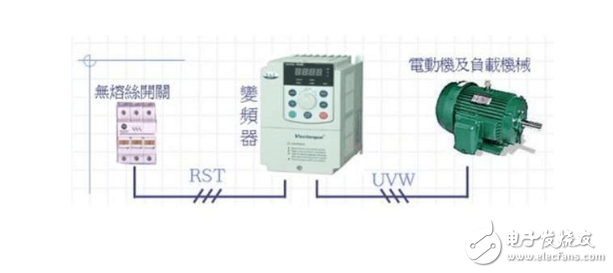
It is the inverter control cabinet. Because the central air conditioning system is designed according to the maximum load and a certain margin, in fact, in the middle of the year, the operation under full load is only more than ten days, even more than ten hours, almost most of the time load. All run below 70%. Usually, the load of the freezing main unit in the central air-conditioning system can automatically adjust the load according to the seasonal temperature change, but the refrigerating pump and the cooling pump matched with the freezing main machine can not automatically adjust the load, and operate under the load of 100% for a long time, resulting in the energy pole. The waste is also aggravating the operating environment and operating quality of the central air conditioner. With the increasing maturity of frequency conversion technology, the combination of frequency converter, PLC, digital-to-analog conversion module, temperature sensor, temperature module and other components is combined to form a closed-loop automatic control system for temperature difference, which automatically adjusts the output flow of the water pump; It can maintain the room temperature in the desired state, make people feel comfortable and satisfied, can make the whole system work smoothly and stably, and more importantly, its energy-saving effect is as high as 30% or more, which can bring good economic benefits. Inverter control cabinet (inverter electrical control cabinet / electric control cabinet / electric control box) using the electrical control developed by Siemens, ABB, Schneider, Fuji, Mitsubishi, Panasonic, Delta, Shihlin, Huichuan and other manufacturers of inverters Cabinet, AC input reactor, output reactor, DC reactor and EMI filter, brake unit, braking resistor, contactor, intermediate relay, thermal relay, programmable controller can be installed in the frequency conversion cabinet according to working conditions. (PLC), programmable operation terminal (GOT), watt-hour meter, cooling fan, etc., according to system conditions, set various control buttons and indicators on the inverter cabinet panel such as forward rotation, reverse rotation, motor speed increase, motor deceleration , jog forward rotation, jog reversal, manual / automatic, emergency stop, frequency / power frequency, PLC control, touch screen, etc., currently more stereotyped: constant pressure water supply frequency control cabinet (1 control 1, 1 control 2, 1 control 3, etc.), escalator frequency conversion control cabinet, central air conditioning circulating water pump frequency conversion cabinet, fan frequency conversion energy-saving cabinet, air compressor constant pressure air supply system (inverter energy-saving soft start control system). How the frequency converter works The main circuit is a power conversion part that supplies a voltage-regulating and frequency-modulated power supply to the asynchronous motor. The main circuit of the frequency converter can be roughly divided into two types: the voltage type is a frequency converter that converts the direct current of the voltage source into an alternating current, and the filtering of the direct current circuit is a capacitor. . The current type is a frequency converter that converts the direct current of the current source into an alternating current, and the direct current loop filtering is an inductance. It consists of three parts, which converts the power frequency power supply into a "rectifier" of DC power, absorbs the "flat wave loop" of the voltage ripple generated by the converter and the inverter, and converts the DC power into the "reverse" of the AC power. Transformer." Inverter wiring diagram Inverter wiring method 1. The power supply should be connected to the R, S, T terminals of the inverter input terminal, and must not be connected to the inverter output terminals (U, V, W), otherwise the inverter will be damaged. After wiring, the broken wire ends must be cleaned, and the broken wire ends may cause abnormalities, malfunctions and malfunctions, and the frequency converter must always be kept clean. When punching holes in the console, be careful not to let debris powder enter the inverter. 2. Do not connect anything other than the recommended brake resistor option between terminals + and PR, or never short circuit. 3. Electromagnetic interference, the input/output (main circuit) of the inverter contains harmonic components, which may interfere with the communication equipment near the inverter. Therefore, install the optional radio noise filter FR-BIF or FRBSF01 or FR-BLF line noise filter to minimize interference. 4. In long-distance wiring, due to the influence of the parasitic capacitance charging current of the wiring, the fast response current limiting function is reduced, and the instrument connected to the secondary side malfunctions to cause a malfunction. Therefore, the maximum wiring length is smaller than the specified value. When the length of the wiring must be exceeded, it is necessary to put Pr. 156 is set to 1. 5. Do not install power capacitors, surge suppressors and radio noise filters on the output side of the inverter. Failure to do so may result in damage to the drive or damage to the capacitor and surge suppressor. 6. In order to make the voltage drop within 2%, the appropriate type of wire should be used. When the wiring distance between the inverter and the motor is long, especially in the case of low frequency output, the torque of the motor will drop due to the voltage drop of the main circuit cable. 7. After the operation, the operation of changing the wiring must be performed after the power is cut off for more than 10 minutes, and the voltage is checked with a multimeter. There is still a dangerous high voltage on the capacitor for some time after the power is turned off. The control circuit of the frequency converter can be roughly divided into analog and digital. 1. The wiring of the control circuit terminals should be shielded or twisted, and must be routed separately from the main circuit and the high-voltage circuit (including the 200V relay program circuit). 2. Since the frequency input signal of the control circuit is a small current, in the case of contact input, in order to prevent poor contact, the small signal contact should use two parallel nodes or use twin contacts. 3. The wiring of the control circuit is generally selected from 0.3 to 0.75 square meters. 1. Since there is leakage current in the inverter, in order to prevent electric shock, the inverter and motor must be grounded. 2. Dedicated grounding terminal for inverter grounding. For the connection of the grounding wire, use tinned crimp terminals. When tightening the screws, be careful not to break the turnbuckle. 3. Lead is not contained in tin plating. 4. The grounding cable should be as thick as possible. It must be equal to or greater than the specified standard. The grounding point should be as close as possible to the inverter. The shorter the grounding wire, the better. 1. The inverter itself has strong electromagnetic interference, which will interfere with the operation of some equipment. Therefore, we can add a cable sleeve to the output cable of the inverter. 2. The control line in the inverter or control cabinet is at least 100mm away from the power cable. 3. There will be a description of the inverter when purchasing the inverter. If not, you can download it from the official website of the brand you purchased. The above contents of the inverter manual are quite detailed, including product introduction, working principle, installation and debugging, and so on. Pcb/Fpc Membrane Keypad,Membrane Keyboard,Fpc Membrane Keyboard,Customized Membrane Keypad CIXI MEMBRANE SWITCH FACTORY , https://www.cnjunma.com


