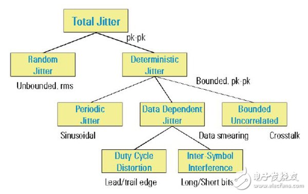
Preface With the increasing use of SERDES and the increasing speed, the problem of SI is becoming more and more important. It has a very important guiding role for PCB design and SERDES parameter optimization. Device selection also begins with SI simulation. But in the simulation, the tool will let the user set some information, such as jitter, swing, pre-emphasis and so on. Both swing and pre-emphasis can be found in the manual. But the setting of jitter does not have a clear guide. And different jitter settings will give completely different results. So wrong settings tend to mislead our design and optimization. In particular, the device evaluation stage will also determine the success or failure of device selection. This short article is a simple guide to setting up jitter in your simulation. In terms of jitter, jitter is the offset of the edge of the signal from the ideal position. On an oscilloscope, if there is no jitter, we can see that the signal edge should be a clear line. But because of the existence of jitter, what we see on the edge is a blurry piece. According to the characteristics of jitter and its formation, jitter can be divided into two types: random jitter (RJ: Random Jitter) and deterministic jitter (DJ: Determinis TIc Jitter). Random jitter RJ When we want to approximate the conversion between RMS and peak-to-peak value, we need a conversion coefficient, which has corresponding values ​​according to different bit error rates, as shown in the following table: Deterministic jitter DJ There are 3 basic classifications for deterministic jitter Data Dependent Jitter (DDJ: Data Dependent Jitter) 1. Duty Cycle Distortion (DDC: Duty Cycle DistorTIon) 2. Inter-Symbol Interference (ISI: Inter-Symbol Interference) Periodic jitter (PJ: Periodic Jitter) Bounded uncorrelated jitter (BUJ: Bounded Uncorrelated Jitter) The periodic jitter PJ is a jitter signal that recurs over a certain period or frequency, which is equivalent to one frequency modulation of the signal. Therefore, it will be seen that the periodicity of the signal period becomes larger and smaller. Bounded uncorrelated jitter BUJ is mainly caused by electromagnetic interference (EMI) and crosstalk. Among them, crosstalk is the main cause of BUJ. Due to the randomness of crosstalk formation, BUJ is bounded, but it has nothing to do with the data pattern. By the way, this jitter is not compensated on the receiving side. When testing the received jitter tolerance, the BUJ is inserted. Data-dependent jitter DDJ Due to the "memory" effect of the electrical or optical system, the current bit transition time is introduced by the influence of the previous bit transition time. It is related to the pattern of the data, which is closely related to the Run Length, and the other is the duty cycle distortion. At the same time, the DDJ is also related to the impact/step response of the channel or medium through which the signal passes. ISI occurs due to the different run lengths of different data patterns, resulting in uneven pulse transitions. The biggest interference comes from the interference between short pulses and long pulses of opposite polarity, and vice versa. Deterministic jitter measures peak-to-peak values ​​in ps or UI. For ease of understanding, the following is the entire classification of jitter: For a detailed description of the jitter, there is a lot of information to check, so here is a brief explanation to facilitate understanding of the following topic. The handling of jitter in XILINX's IBIS-AMI model is as follows: 1. PJ, DCD and other DJ These SERDES inherent jitter elements are included in the modeling, so in the EDA/simulation tool, the corresponding value can be safely set to 0; 2. RJ is required by the user to set it up; 3. ISI is related to the line, so this DJ element will be reflected in the simulation and does not need to be set on the TX side (otherwise it will be counted again). Jitter settings in the simulation Jitter setting After each chip of XILINX comes out, there will be a feature report. In the simulation, we need to use the Generic CharacterizaTIon Report, because this is the result of high-volume testing. Here we take the simulation of GTX on ADS as an example, the line rate is 9.8304Gbps. In the simulation, we need to look at the eye diagram of the TX signal after a PCB trace. One thing to note is that in ADS, the bit-by-bit mode is consistent with the simulation results. Especially when we add EYE_PROBE_DIFF in the middle of the line, the result of the STATISTIC mode is not available. The model on the receiving side is an IDLE_RX. It has no equalization settings and is only equivalent to a terminal match. This is to be able to objectively display the far-end eye diagram, not the eye diagram after RX equalization. From the S-parameters of the channel (including the FPGA package and the PCB trace), the insertion loss at 4.9152 GHz is From the Generic Characterization Report of K7 GTX, we can see the transmit jitter at the 9.8304 Gbps rate on the transmitting side. The RJ in the table is the peak-to-peak value. Both TJ and DJ, RJ, have MIN and MAX values. But it is not simply a simple addition of DJMAX and RJMAX is TJMAX. These are the respective maximum values, but the channel that is not the largest DJ has the largest RJ. The simple addition of values ​​from the table also indicates that this is not the case. So when we select the parameter, we choose the maximum value MAX, 0.114 UI. In the ADS settings, RJ is the RMS value. Since the bit error rate we set is 1E-12, RJ needs to be divided by the factor 14.069: As mentioned earlier, the reason for ISI is that the uneven pulse edge is caused by its "memory" effect after being routed through the PCB. This is the inevitable effect of the signal passing through the transmission line. So this cannot be set in the DJ on the sending side, otherwise the value of ISI will be calculated repeatedly. Simulation Results Since the signal needs to go through a PCB, we also set a pre-emphasis on the transmitting side. Below is the result when the swing is 677mV. Due to the PCB board, the jitter of the far-end eye is larger than the value reported by the feature. This is understandable. Summary In the simulation of SERDES, the correct setting of jitter is crucial. Open Type Braided Sleeve,Braided Sleeving,Braided Cable Sleeve,Braided Sheath Shenzhen Huiyunhai Tech.Co., Ltd. , https://www.cablesleevefactory.com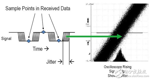
Random jitter is caused by random noise such as thermal noise and shot noise. Its distribution is consistent with a Gaussian distribution. Since the tail of the Gaussian distribution expands to infinity, the peak-to-peak value of RJ has no boundary. RJ's root mean square (RMS: Root Mean Square) converges to the width of the Gaussian distribution. So random jitter generally measures its rms value in ps RMS or UI RMS. 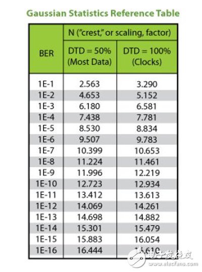

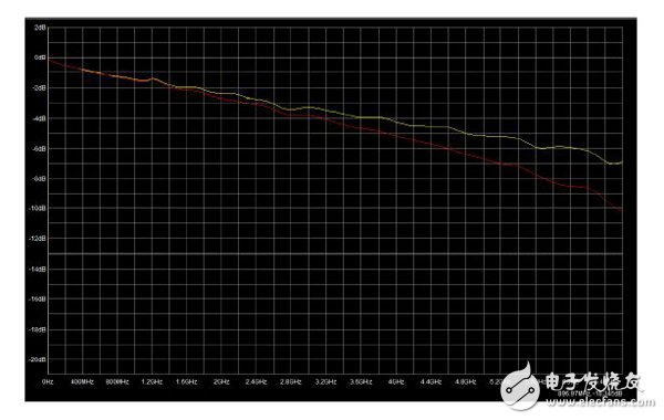
1. Single-ended (red): -6.5dB
2. Differential (yellow): -5.1dB 
0.114/14.069 = 0.0081 UI 
TXPRECURSOR = 3 (0.68dB)
TXPOSTCURSOR = 8 (1.94dB) 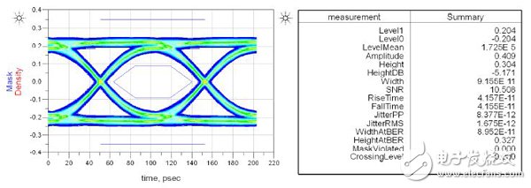
In the IBIS-AMI model of XILINX SERDES, the main elements of the DJ have been included, and ISI is the signal introduced through the transmission line. So in the simulation, DJ is set to 0, and RJ is the maximum value of the SERDES Generic Characterization Report to get the worst result.