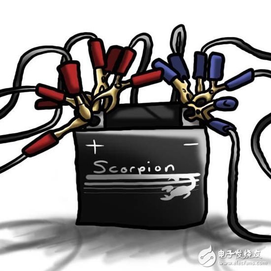
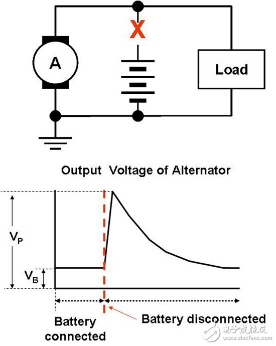
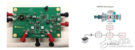
You are more likely to have a similar experience when starting a car, that is, only hear the hum, not the sound of the engine. This is caused by the battery being dead. Although there are many reasons for the battery being out of power, in most cases, it is caused by human error (is it not closed in the car?) Human error will still be in Occurs when the car is started by a line. Figure 1 - Battery when the cable is properly connected. Automotive system designers must be prepared to deal with two types of errors that may be caused by a broken line: reverse battery, dual battery. When the red end of the jumper cable is connected to the battery ground, and the black end is connected to the positive pole of the battery, the battery reverse connection occurs. The situation at this time is exactly the opposite of the connection in Figure 1. In such cases, a diode will protect the system, but at the same time, a diode will cause system losses during normal operation. The forward voltage drop can be any value between 0.5V and 1.0V, depending on the system power rating. This produces a lot of heat and reduces overall system efficiency. Trucks and buses have two batteries connected in series, and the car has only a single battery. There may be only trucks in the vicinity that can give your car a line. This creates a two-battery situation where the voltage applied to the entire system is now doubled. This puts a lot of pressure on the system. Load dumping is another situation that engineers must be able to withstand and overcome when designing a system. Since it is related to the problem of the system itself, this situation is not caused by human error such as reverse battery connection. Figure 2 - Diagram of the load dump situation. The throw load (as seen in Figure 2) occurs when the alternator or battery is disconnected from the system due to corrosion or even worse installation. This disconnect creates a large voltage spike that can penetrate the entire system. Alternators play an important role in the operation of automotive power systems. Without it, your battery will be out of power. All of these discussed situations pose a major challenge to the automotive front-end design of how to protect control components, sensors, and entertainment systems from unwanted surges, voltage transients, electrostatic discharge (ESD), and noise that appears on power lines. The Transient Voltage Suppressor (TVS) is a low-cost solution for automotive electronic protection and has several important parameters for these automotive applications, including power rating, cut-off voltage, breakdown voltage, and maximum breakdown voltage. Since TVS does not suppress all problems, you must also ensure that the downstream DC/DC converter you use has a higher VIN, so that there is no spike in the system. In front-end power supplies, switching regulators are critical to the overall power density and efficiency of the system when the system converts the battery voltage to the voltage required by the processor. The problem with switching regulators is that they generate noise during operation. The switch needs to quickly change electrical conditions; this includes current entering the switch; switching node voltage variations; and output voltage ripple, as well as other factors associated with external component selection. When controlling a large amount of electrical energy circulating in many directions, some of these factors cannot be changed due to physics. All of these conditions have an impact on electromagnetic compatibility, referred to as EMC. The main standard of automotive EMC is called CISPR 25, which includes several grades, the grade is divided according to the strictness of the requirements of the interrupted equipment, and the EMC required. You often hear the noise generated by the EMC on the AM band of the radio. This noise is annoying, so filtering is needed to suppress this noise. Automotive-specific switching regulators are designed to pass through a combination of architecture (current mode is the most common architecture in automotive applications), component placement (as close as possible to the switching regulator, as few as possible), and device pin assignments. It is possible to reduce electromagnetic noise. You can never eliminate this noise, but you can reduce them. At TI, we developed a reference design that enables front-end automotive power supply designers to meet all of these automotive system standards and address the issues discussed in this blog post. Figure 3—TI's CISPR 25 Class 5 Multiple Output Reference Design for Automotive Rear Camera and Advanced Driver Assistance System (ADAS). The TI Designs reference design shown in Figure 3 is an electromagnetic interference (EMI) optimized multi-output design that complies with CISPR 25 Class 5 automotive standards. The 9W design is ideal for a wide range of VIN Automotive Advanced Driver Assistance Systems (ADAS) applications that support cold start conditions. This reference design features the LM53603-Q1 DC/DC regulator (used as a buck), the LM26420 DC/DC regulator (used as a dual buck), and the TPS60150 switched capacitor voltage converter (used as a charge pump for a 5V output) ). This design accepts input voltages from 4.5VIN to 20VIN and provides 3.3V, 2.5V, 1.8V, and 5V at 1.0A, 1.0A, 1.0A, and 100mA, respectively. It is small, inexpensive, efficient, and can be customized for ADAS and other automotive-related applications. The four-layer printed circuit board (PCB) measures 65mm x 100mm. Shenzhen Esun Herb Co.,Ltd. , https://www.szyoutai-tech.com