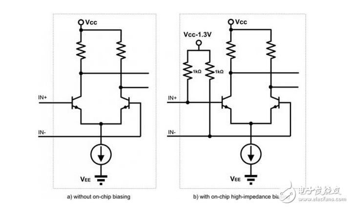
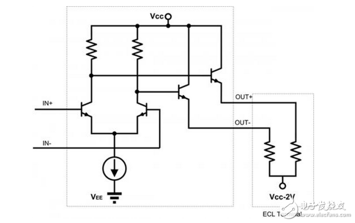
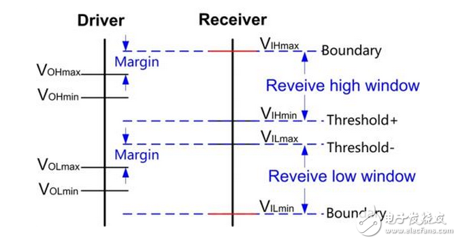
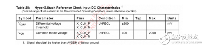
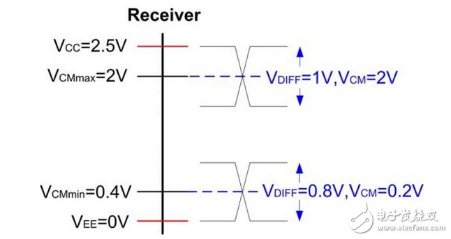
The ECL circuit (ie Emitter-Couple Logic) is an unsaturated digital logic circuit in which the transistor operates in a linear or cut-off region, and the speed is not limited by the storage time of minority carriers. It is the fastest of the various logic circuits available and can handle operating rates up to 10Gbps. The ECL standard was first proposed by Motorola. The main classifications of ECL are as follows. PECL is PosiTIve Emitter-Couple Logic, which means positive emitter-coupled logic, using a 5.0V power supply. PECL evolved from ECL, which is Emitter-Couple Logic, which is the emitter-coupled logic. The ECL has two supply voltages, VCC and VEE. When VEE is grounded, when VCC is connected to positive voltage, the logic at this time is called PECL; when VCC is grounded, when VEE is connected to negative voltage, the logic at this time becomes NECL, VEE is generally connected to -5.2V power supply; generally narrow ECL is Refers to NECL. Since PECL/LVPECL can share a positive supply with other circuits in the system, PECL/LVPECL is more widely used than ECL. At the beginning of the PECL device, VCC was connected to +5V. Later, in order to directly utilize the widely used 3.3V and 2.5V voltages, LVPECL (Low Voltage PECL) with VCC=3.3V/2.5V appeared. LVPECL is Low Voltage PosiTIve Emitter-Couple Logic, which is low voltage positive emitter coupling logic. Using 3.3V or 2.5V power supply, LVPECL is evolved from PECL. The input to PECL is a differential pair with a high input impedance. The common-mode voltage of this differential pair needs to be biased to VBB = VCC-1.3V, which allows the input signal level to be dynamically dynamic. For the input stage of different chips, the common mode level allowed by the signal may be different, please refer to the corresponding datasheet. Some chips have integrated bias circuits internally, which can be directly connected during use. Some chips are not added, and DC bias is required outside the chip for use. The standard output load of PECL is in the range of 50 ohms to VCC-2V. Under this load condition, the common mode voltage of OUT+ and OUT- is VBB=VCC-1.3V, and the average current of the output of OUT+/OUT- is 14mA. 1. Advantages of ECL logic: 1) Strong fan-out capability. The ECL output impedance is low (6~8 ohms) and the output impedance is high (usually 10kohm), so the fanout factor is very high. 2) Low noise and low power requirements. ECL/PECL devices are less sensitive to synchronous changes in supply voltage, so the requirements for power supply ripple, skew, and distribution can be relatively relaxed in certain ECL applications. Sometimes the circuit's power supply voltage range is allowed to be as wide as 10%. Since the two circuits of the differential circuit work alternately, the power supply current is basically constant during the operation of the circuit (does not change with the change of the logic state, and does not increase with the increase of the operating frequency), so it is considered to relax the requirement for the internal resistance of the power supply. 3) Fast speed. When the transistor is in operation, it does not enter the saturation state, only works in the linear region and the cut-off region. There is no storage phenomenon of minority carriers, the switching time is greatly shortened; the collector junction capacitance is greatly reduced, and the RC time constant is also reduced accordingly. The transmission delay time is very short; the logic level swing of the circuit is small (single-ended less than 850mV), and the voltage change on each junction during the dynamic conversion process has a short charge-discharge time for the junction capacitance (including parasitic capacitance). 2. Disadvantages of ECL logic: 1) The shortcomings of ECL are also obvious, that is, the power consumption is large. It can be said that the high-speed performance of ECL is exchanged for the high power consumption. The difference between the high and low levels of the ECL logic is typically 800mV, and its center reference level (common mode voltage) VBB varies according to VCC, typically VCC-1.3V. Therefore, the level of PECL varies with VCC. Such as: PECL: VBB=5V-1.3V=3.7V, VOH=4.1V, VOL=3.3V; LVPECL: VBB=3.3V-1.3V=2V, VOH=2.4V, VOL=1.6V; VBB=2.5V-1.3V=1.2V, VOH=1.6V, VOL=0.8V; NECL: (VEE = -5V, -3.3V, -2.5V; VCC = 0V), VBB = 0V - 1.3V = -1.3V, VOH = -0.9V, VOL = -1.7V. Of course, the above DC characteristics are only for the general, in fact, will be slightly different to the specific device, the input and output of the same device are also different. At the time of design, you should refer to the corresponding device's datasheet to obtain its accurate electrical characteristics. Another important point about the DC characteristics is the interface matching between the two ECL devices. That is, we have to pay special attention to whether the Driver's output is within the tolerance of the Receiver's input. We call this tolerance range "receiving window". If the output of the Driver does not fall within this receiving window, it may cause a misjudgment at the receiving end, resulting in a design failure. So look at whether the two ECL devices can be interconnected. For the Driver, as long as it is the range of VOL whose output high level VOH and output low level are obtained from DATASHEET; for Receiver, just look at some indicators about the receiving window, Two situations. If the ECL is used as a single-ended signal (this is not the case), the method of interconnect analysis is similar to the method of single-ended signals such as LVTTTL, COMS. Need to pay attention to the input high level VIH and input low level VIL maximum and minimum values, VIH maximum and minimum constitute the VIH receiving window, the maximum and minimum VIL constitute the VIL receiving window. As shown below: When the VOH range of the Driver all falls within the VIH window of Receiver, the VOL range of the Driver all falls within the VIL window of Receiver, which can ensure that Receiver can correctly receive the output of the Driver, otherwise there will be potential interconnection incorrectly or even The possibility of damaging the device. For differential signals, the indicators to focus on are the input common mode level VCM and the differential signal VDIFF range. For example, an input port of a device works in LVPECL mode. Its indicators are as follows (AVDDH=2.5V): Then its receiving window is shown in the figure below, which shows the maximum single-ended voltage allowed when the common mode voltage is maximum or minimum. As long as the differential signal falls within this range, it satisfies at the same time: 1. Output |VDIFF| is greater than 300mV; 2. The output common mode signal VBB is located between 400 mV and 2000 mV; 3. The output single-ended signal cannot exceed VCC or VEE; Differential signals that satisfy the above conditions can be received correctly. It can be noted that if the common mode signal is terminated to VBB = VCC - 1.3V, the acceptance window is maximum. As can be seen from the above, differential signals have a much wider receive window than single-ended signals, which is one of the reasons why differential signals are commonly used in high-speed applications. Mini Box,Intel Celeron Processor Mini Pc,Customizable Pc,Mini Pc Desktop C&Q Technology (Guangzhou) Co.,Ltd. , https://www.gzcqteq.com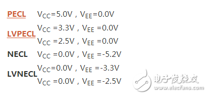
What are the ECL PECL LVPECL signals? Their advantages and disadvantages and detailed analysis of the circuit diagram
Introduction to ECL Circuit