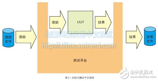
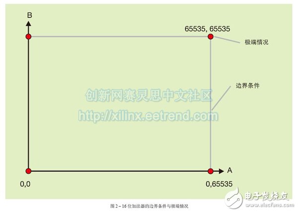
Verifying that the RTL module or FPGA meets the requirements can be challenging. However, some methods can be used to optimize the verification process to ensure successful verification. Validating an FPGA or RTL module can be a very time consuming process because engineers must make every effort to ensure that the design operates correctly in accordance with the specifications and in extreme conditions that can cause module errors. Engineers typically use a test platform for verification purposes. A test platform is a file created for test design. However, the test platform can be simple and versatile. Let's take a look at how to make the most of the test platform without making it too cumbersome. What is verification? Given the size and complexity of modern FPGA designs, ensuring that UUTs operate according to specifications can be a daunting task. Therefore, the engineering design team must determine which verification strategy to use at the beginning of the project. The selection strategy skills are as follows: Boundary conditions mean that one of the inputs reaches the extreme value, and the extreme case is that all inputs reach the extreme value. Regardless of which verification strategy is used, the engineering team needs to develop a test plan that dictates how each module and final FPGA are validated and meets all requirements. The test platform created by the self-test platform to stimulate the UUT can be either self-test or non-self-test. If you prefer to use a non-self-test, you need to visually look at the test results on your computer monitor to make sure the test platform works as expected. The difference between the self-test test platform and the traditional test platform is that in addition to the application of the stimulus, the output of the UUT is checked according to the expected result, as shown in Figure 1. This will clearly indicate whether the UUT passed the test. Combine this with the control and reporting capabilities of text files to create a very powerful verification tool. The self-testing test platform has several advantages. First, this method of visualizing simulated waveforms with the naked eye is time consuming and extremely complex, and the self-testing platform saves you the labor costs. In addition, the self-test platform provides comprehensive and comprehensive pass or fail reports that you can save and use as test credentials in subsequent design flows. If the UUT needs to perform design iterations at a later stage, then returning to the test platform and determining whether the test passes or fails (this process is often referred to as a regression test process) takes much less time than using a traditional test platform. Extreme Conditions, Boundary Conditions, and Stress Testing The purpose of the test platform is to ensure that the module is executed according to functional requirements, any extreme conditions can be resolved, and, most importantly, the test platform should fully implement the UUT code. Therefore, when validating the design module, the "glass box" test method is often used because it can understand and observe the internal condition of the UUT module. In contrast, when the UUT is an FPGA, you need to use the top-level black box test because the top layer requires longer verification and simulation time. In order to verify the functionality of the design as required, the incentives applied to the test platform must be the same as those expected to be seen by the module during operation. However, testing all possible inputs to prove functional compliance can be a very time consuming process. Therefore, engineers will focus on boundary conditions and extreme conditions and test some typical operational values. Boundary conditions mean that one of the inputs reaches the extreme value, and the extreme case is that all inputs reach the extreme value. An example of a better representation of these two cases is a simple 16-bit adder that accumulates two values ​​and produces a result. Figure 2 shows the boundary conditions and extremes in this case. You can clearly see that the extreme case is when both A and B inputs are equal to 0; when A is equal to 0, B is equal to 65535; when both A and B are equal to 65535; and when A is equal to 65535, B is equal to zero. Boundary conditions are values ​​between extreme cases. For some applications, the UUT may be stress tested to ensure a margin outside of normal operation. The stress test will vary depending on the module, but may involve repeated operations, causing the buffer and FIFO to overflow. Stress testing the design reduces the chances of the verification engineer damaging the UUT. Basic Features Din Rail Terminal Block,Din Rail Fuse Terminal Block,Din Rail Busbar Terminal Block,Din Rail Power Terminal Blocks Sichuan Xinlian electronic science and technology Company , https://www.sztmlch.com
Verification means ensuring that the unit under test (UUT) meets both the design requirements and the design specifications for its intended purpose. In many cases, the verification work is performed by a team other than the design team, and the project has a new understanding. In this way, the person who designs the UUT is not the one who determines whether it can work correctly.
Functional Simulation Only - This technique checks if the design is working correctly.
Functional Simulation and Code Coverage - This method checks the correctness of the function and checks that all code in the design has been tested.
Gate Level Simulation - This technique also verifies the functionality of the design. Performing this simulation method can take a lot of time when back-end annotations are made with timing information from the final implementation.
Static Timing Analysis - This method analyzes the final design to ensure that the module achieves timing performance.
Form Equivalent Verification - Engineers use this technique to check the equivalence of netlists and RTL files. 

1. The terminal has universal mounting feet so that it can be installed on U-rail NC 35 and G-rail NC32.
2. The closed screw guide hole ensures ideal screwdriver operation.
3. Equipped with uniform accessories for terminals of multiple cross-section grades, such as end plates, grouping partitions, etc.
4. Potential distribution can be achieved by inserting a fixed bridge in the center of the terminal or an edge-plug bridge inserted into the wire cavity.
5. The grounding terminal and the N-line slider breaking terminal with the same shape as the common terminal.
6. Using the identification system ZT, unified terminal identification can be realized.
7. The rich graphics enhance the three-dimensional sense of the wiring system.