Radio frequency identification technology is a non-contact automatic identification technology. It is a short-range wireless communication system consisting of an electronic tag (Tag/Transponder), a reader/writer (Reader/Interrogator), and a middleware (Middle-Ware). The tag in radio frequency identification is a combination of a radio frequency identification tag chip and a tag antenna. Tags are classified into active tags and passive tags depending on their mode of operation. The active tag itself carries the battery to provide the energy required for the reader to communicate: the passive tag uses an inductive coupling or backscatter mode of operation, ie an energy-activated chip is obtained by an electromagnetic field or electromagnetic wave emitted from the reader through the tag antenna, and The degree of matching between the RFID tag chip and the tag antenna is adjusted, and the information stored in the tag chip is fed back to the reader. therefore. The impedance of the RFID tag antenna must be conjugated to the input impedance of the tag chip to allow the tag chip to maximize the electromagnetic energy emitted by the RFID reader. In addition, the design of the tag antenna must also consider the application of the electronic tag, such as the tag antenna applied to the surface of the metal object and the tag antenna applied to the surface of the ordinary object, there is a big difference in the structure and material selection of the antenna. It is suitable for a variety of chips, low-cost, multi-purpose tag antenna is one of the key technologies for radio frequency identification in China. For RFID systems with passive tags, there are two modes of operation depending on the operating frequency band. One is the Induct.TIveCoupling T mode, also known as the near field mode, which is mainly used for low frequency and high frequency RFID systems: the other is Backscattering 32 Mode, also known as far-field T mode, is mainly used in UHF and microwave RFID systems. The inductive coupling mode mainly means that the reader antenna and the tag antenna are in the form of coils. When the reader reads the tag, it sends an unmodulated signal. After the electronic tag antenna in the near field of the reader antenna receives the signal and activates the tag chip, the tag chip controls the current in the tag antenna based on a globally unique identification number (ID) stored internally. This current magnitude further enhances or reduces the magnetic field emitted by the reader antenna. At this time, the near-field component of the reader exhibits the modulated characteristics, and the internal circuit of the reader detects 0 to the amount of modulation generated by the tag and demodulates and obtains the tag information. In the backscatter T mode, electromagnetic waves are used between the reader and the electronic tag for information transmission. When the reader reads and recognizes the tag, the unmodulated electromagnetic wave is first emitted. At this time, the electronic tag antenna located in the far field receives the electromagnetic wave signal and generates an induced voltage on the antenna, and the internal circuit of the electronic tag rectifies the induced voltage. And zoom in to activate the tag chip. After the tag chip is activated, the impedance of the tag chip is changed by its own global unique identification number. When the impedance between the impedance of the electronic tag chip and the tag chip is better, the signal is not substantially reflected, and when the impedance matching is not good, Almost all of the signal will be reflected. In this way, the amplitude of the reflected signal changes, which is similar to the amplitude modulation of the reflected signal. The reader determines the identification number of the electronic tag by receiving the modulated reflected signal and identifies it. Such antennas mainly include a microstrip antenna, a planar dipole antenna, and a loop antenna. Figure 2 shows the UHF electronic tag antenna that we have developed to work in a variety of identification environments. As mentioned above, the radio frequency identification system for low frequency and high frequency uses the inductive coupling mode for communication, so the reader and the electronic tag for the two frequency bands use the antenna in the form of a coil. The radio frequency identification system in which T is used in both frequency bands is subject to the near-field effect, resulting in a shorter recognition distance. According to the current situation, the maximum recognition distance of the RFID system using near field communication is less than 1 meter. Since the RFID system in the low frequency and high frequency bands uses the electromagnetic field coupling mode, the antennas in the system are in the form of coils. The main reasons for adopting this form are as follows: 1. The coupling of the electromagnetic field is relatively tight between the coils: 2. The antenna in the form of a coil further reduces the volume of the antenna and thus reduces the volume of the tag: 3. The characteristics of the tag chip require that the tag antenna have a certain reactance. In the ultra-high frequency and microwave bands, the communication between the electronic tag and the reader uses backscattering. At this time, the bridge connecting the electronic tag and the reader is no longer a near magnetic field but an electromagnetic wave. At this time, the passive electronic tag is in the far field of the electromagnetic wave of the reader. The distance between the far field of the RFID system and the reader/writer in the frequency band can be calculated according to the wavelength of the frequency band and the aperture of the antenna. In general, passive tags in the UHF range can be up to 10 meters away, according to available data. The passive tag working in the microwave band (mainly 2.45 GHz) has a working distance of only about 1 meter. Therefore, the current RFID system using the backscattering mode mainly uses the UHF band located at 860-960 MHz. In a radio frequency identification system consisting of a passive tag antenna, the tag needs to obtain an energy-activated tag chip from an electromagnetic field or electromagnetic wave generated by the writer. Therefore, some circuits in the electronic tag are specifically used to detect the induced electromotive force or induced voltage on the tag antenna, and are rectified by a diode circuit and amplified by other circuits. These circuits are integrated inside the tag chip. A portion of the distributed capacitor is typically introduced when the chip is packaged. However, the antenna design itself does not need to know the specific circuit in the chip, but only needs to grasp the chip and the chip impedance after the package, and use the law of maximum energy transfer to design the input impedance of the antenna.
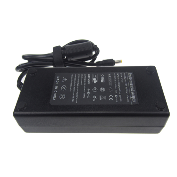
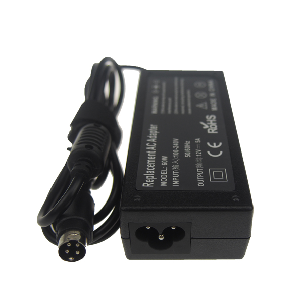
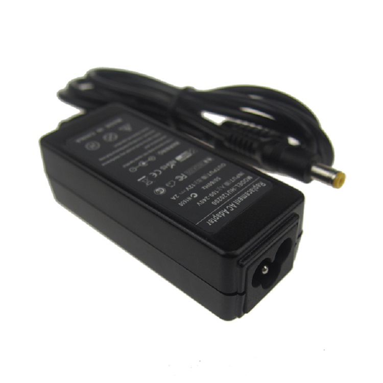
12V Adapter also called 12V AC DC adapter, the input of 12V power adapter is 100v-240v 50/60HZ suit for worldwide use.
All
our 12v ac adapter with over current protection, over load protection, short
circuit protection, over heat protection.when use it can safeguard your
equipment.
Usually our dc Cable and ac cable compatible with the 12v power adapter is 1.2m, we can also customized the length as your requests according to your devices.
if the adapter you need is not 12V, pls contact us freely, we can also customized the adapter output can your demands. OEM&ODM orders are highly welcomed!
12V Adapter,12V DC Adapter,12V Power Adapter,12V DC Power Adapter Shenzhen Yidashun Technology Co., Ltd. , https://www.ydsadapter.com
Yidashun can produce 12v power supply from 12V 1A~12V 16A MAX. This power adapter mostly make as dc size 5.5*2.1mm, 5.5*2.5mm, round 4 pin used for led lights, CCTV camera, LCD TV, set-top box and so on. All our adapter with full power and can be used for different devices run constantly each day.


