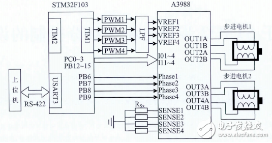
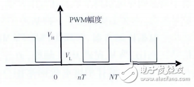
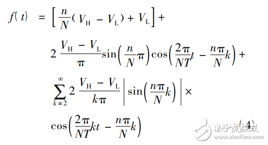
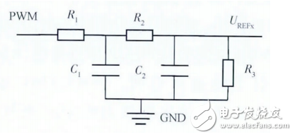
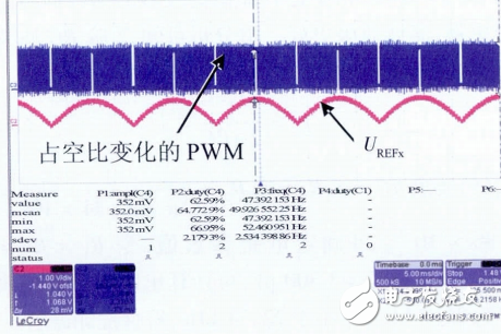
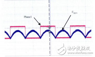
This paper mainly introduces a hybrid stepping motor control scheme based on STM32. STM32 generates PWM (pulse width modulation signal), completes DAC conversion by PWM, and realizes multi-segment control of stepping motor through the output voltage of PWMDAC. Compared with the design scheme of the DAC digital-to-analog conversion chip, the design has the advantages of simple circuit and high cost-effectiveness, and can realize the driving control of the stepping motor by one-sixteen steps, and the precision is high. The hardware design block diagram is shown in Figure 1. The PC host computer sends control commands to the STM32F103, and controls the A3988 through the STM32F103 to drive the two stepper motors to rotate. Among them, STM32F103 is an ARMCortex-M3 core-based microcontroller manufactured by STMicroelectronics. It has advanced core architecture, superior performance, frequency up to 72MHz, high execution efficiency, high computing power and data processing functions. The peripheral interface, in the hardware design, the RS-422 serial communication between the host computer and the STM32F103 is realized by an external MAX3079 level conversion chip. Figure 1 hardware design block diagram The STM32F103 controls the timer to generate the PWM, implements the PWM DAC conversion through the LPF (Low Pass Filter), and provides the four reference voltages of the A3988 by the PWMDAC. In the design, the output channel of the timer TIM1 is filtered and the A3988 is used. The reference voltage VERFx interface is connected, PC0~3, PB12~15, PB6~9 are general-purpose GPIO output ports, connected to A3988 logic control signal input pins I0x, I1x and Phasex, PC0~3 and PB12~15 respectively, Phasex Controls the direction of current flowing through the phases of the motor. The stepping motor used has a step angle of 0.9 and a rated current of 0.5A. The motor is selected as a two-phase stepping motor, assuming that the phases are A and B. The current through the two phases is 90 in phase, and the magnitude and direction of the current flowing through the two phases can be controlled to control the rotation of the motor. The A3988 is a 4DMOS full-bridge pulse-width modulated motor driver that can drive two stepper motors simultaneously, with a maximum bridge output current of up to 1.2A. Each phase current flowing through the motor can be controlled by UREFx, I0x, I1x, Phasex and resistor Rx connected to the SENSEx pin. The working current can be obtained by the formula (1). ITripMax=UREFx/(3RSx)(1) From equation (1), the maximum current ITripMax is determined by both UREFx and RSx. UREFx is the output voltage of the PWM-DAC. The maximum value is 1.1V, and the RSx uses a 1Ω resistor. ITrip=(%ITripMax/100)ITripMax(2) In equation (2), ITrip is the actual output current, logic interface I0x, I1x control %ITripMax, as can be seen from the user documentation of A3988, when I0x, I1x control logic are low, the actual output current is equal to the maximum current, by the above The formula shows that the maximum output of ITrip is about 367mA. In order to realize the multi-subdivision control of the stepping motor, it is necessary to be able to control the two-phase current flowing through the stepping motor. When the reference voltage UREFx is constant, the logic interface I0x, I1x, and Phasex can only be used to realize the stepping motor in one step and half. Step and quarter-step drive control, such subdivision control can not meet the design requirements, in order to get more subdivision, the design uses dynamic change UREFx method to output the dynamically changing current, by how fine the UREFx Sub-control, to achieve multiple subdivisions of ITrip, thus achieving multi-subdivision control of stepper motors. UREFx is output by PWM-DAC, its value changes from 0 to 1.1V, and it is divided into 32 voltage values ​​by the normal rotation curve of 0~π to obtain 32 voltage values, so that the value of PWM-DAC output is 32 values, corresponding to 32 voltage values ​​from 0 to 1.1 V and 32 current values ​​according to sinusoidal law are obtained. The current direction can be controlled by Phasex, and the drive control of the stepping motor 1/16 step can be realized. Although the large-capacity STM32F103 has an internal DAC, more models do not have a DAC. The STM32F03 used in this article does not have a DAC peripheral function. However, all chips of STM32 have PWM output, so PWM-LPF can be used to realize PWM-DAC output, which saves cost. PWM is essentially a square wave signal with a fixed period and a high and low level duty cycle. The typical PWM waveform in the actual circuit is shown in Figure 2. Figure 2 Typical PWM waveform The PWM waveform of Figure 2 can be expressed as a equation (3) using a piecewise function. In equation (3), T is the reciprocal of the counting frequency of the STM32 timer TIM1 (up to 72MHz), N is the number of counting pulses of one cycle of the PWM wave, that is, the value of ARR-1 of STM32, and n is the PWM wave. The number of high-level counting pulses in one cycle, that is, the value of CCRx of STM32, respectively, VH and VL are the high and low voltage values ​​of the PWM wave generated by STM32, the high level is 3.3V, the low level is 0V, k is The number of harmonics, t is time. Equation (3) is developed into a Fourier series to obtain equation (4). It can be seen from equation (4) that the first square bracket in equation (4) is a direct current component, the second term is a first harmonic component, and the third term is a higher harmonic component greater than one. The DC component is linear with n, and as n goes from 0 to N, the DC component varies from 0 to 3.3V. This is exactly what the DAC of the voltage output requires. Therefore, if the harmonics other than the DC component can be filtered out, the conversion from the PWM wave to the voltage output DAC can be obtained, that is, the PWM wave can be demodulated by a low-pass filter. Among them, the amplitude and phase angle of the second term are related to n, and the frequency is 1/(NT), which is actually the output frequency of the PWM. This frequency is the basis for designing a low pass filter. If the first harmonic can be filtered out well, the higher harmonics are basically absent. The RC second-order low-pass filter is used to realize the demodulation of the PWM wave. The circuit design is shown in Figure 3. Figure 3 second-order low-pass filter conditioning circuit When the value of N is 256, the resolution of the PWM-DAC is log2(N)=8 bits. Under the 8-bit resolution condition, the influence of the 1st harmonic on the output voltage is not required to exceed the accuracy of 1 bit, that is, 3.3/256 = 0.01289V. It can be known from equation (4) that the maximum value of the first harmonic is 2 & TImes; 3.3 / π = 2.1 V, so the RC filter circuit should provide at least -20 lg (2.1 / 0.01289) = -44 dB attenuation. When the counting frequency of the timer TIM1 of the STM32 is 72 MHz and the resolution is 8, the PWM frequency is 72/256=281.25 kHz. If it is a 1st order RC filter, the cutoff frequency is required to be 1.77kHz, and if it is a 2nd order RC filter, the cutoff frequency is required to be 22.34kHz. In contrast, the second-order filter has stronger signal rejection and better filtering. It can be seen from the analysis that the calculation formula of the second-order RC filter cutoff frequency is: 7.96×10⁻⁵, the circuit parameter value can be determined, let R1=R2=2.4kΩ, C1=C2=3300pF, and the cutoff frequency of Figure 3 can be calculated to be 21.9kHz, which is slightly less than 22.34kHz, which meets the design requirements. After the PWM wave modulation, the maximum DC component of the output is 3.3V, and the UWRx operable voltage ranges from 0 to 1.5V. A 2.4kΩ resistor R3 can be used in series with the filter to achieve the DC component. Pressure conditioning. The software design is mainly related to the design of the motor drive software. Through the control of the timer, the rotation direction and speed of the motor are adjusted. Secondly, the design of the PC host computer control software is mainly developed by the C++Bulider platform. Motor testing. The seven timers in the STM32F103 each have four independent programmable channel output PWM signals. The advanced timer TIM1 is selected, which is clocked by the APB2 bus, set to 72MHz, up (increasing) counting, and the value of the automatic loading register ARR-1 is 256. Therefore, the duty ratio of the PWM wave ranges from 0 to 256. The values ​​of different duty cycles are stored in the capture compare register CCRx of each channel. When programming, the duty cycle of the PWM wave is changed by changing the value of the register CCRx. The duty cycle value is calculated as shown in equation (6). Thus, the value of the duty ratio corresponding to 32 points in the range of 0 to π of the normal rotation curve is obtained. The value of the obtained duty ratio is placed in the defined array Sequence[32]. By looking up the table, the timer TIM1 outputs a PWM wave with a duty cycle change, and the waveform of the UREFx is generated by the filter as shown in FIG. 4. Figure 4 PWM generates UREFx waveform As can be seen from the figure, the output signal UREFx waveform has reached the expected target. Since the appropriate filter parameters are selected, there is almost no large phase difference between the PWM wave and the UREFx. Phase1~Phase4 are used to control the direction of current flowing through each phase of the motor. When Phase1 is 1, the current flows from OUT1A to OUT1B. When Phase1 is 0, the current flows from OUT1B to OUT1A. The other three-phase control principles are the same. Phase1 is illustrated as an example. STM32F103 controls the Phase1 signal through PB6, configures PB6 as the push-pull output port, sets PB6 to 1 in the UREFx odd-numbered period, and sets PB6 to 0 in the even-numbered period. In the 0~2π interval, PB6 will change twice. The Phase1 signal changes as shown in Figure 5. Figure 5 Phase1 signal change waveform Through the control of the current direction of the Phasex signal, the sinusoidal curve of the actual output current ITrip with a period of 2π can be realized, and 64 current values ​​are generated at 0~2π, thereby realizing the stepping can realize one-sixteenth of the stepping motor. Step drive control. Since the currents passing through the A and B phases of the stepping motor are 90 in phase difference, when the phase A leads the phase B, the motor rotates forward, and when the B phase advances A, the motor reverses. Therefore, by controlling the phase difference between the A and B phase currents, the direction control of the stepping motor can be realized, that is, the phase difference of the input reference voltage is controlled. In the software design, the timer TIM1 outputs the PWM wave through the look-up table method. When the initial subscript value of the duty cycle array is used, the PWM outputs corresponding to A and B are 90 different. For example, when the initial duty cycle of the corresponding PWM output of A is Sequence[0], phase B is Sequence[16], so that the reference voltages of the input phases are 90 out of phase. In the case where the step angle is known, the rotational speed of the motor can be controlled by controlling the time interval of change between two adjacent values. The smaller the time interval, the higher the rotational speed and the longer the rotational speed is. In order to obtain a precise time interval between the two value changes, the design is precisely controlled by the timer TIM2. The value of ARR-1 in TIM2 is calculated by equally dividing the 0~π2 sinusoid, which is no longer here. To be described, the timer generates a timer interrupt, and the value of the PWM duty cycle is changed in the interrupt response, and the speed is adjustable by 10 steps. It can be seen that the frequency of both Phasex and UREFx changes when the stepping motor realizes the shift control. Electronic Cigarette,Largest E-Cig Oem,China E-Cig Oem,Vape Pen Oem,Vape Device Oem Shenzhen MASON VAP Technology Co., Ltd. , https://www.masonvap.com